OPERATION
3-22
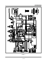
8. Power flows from terminal #8 of the triple pole
double throw relay (12) to a ten second purge
timer (13). This timer allows the combustion
blower (15) to operate for ten seconds allowing
the combustion chamber to clear of any comĆ
bustible gasses.
9. After the timer times out the voltage is applied
to the other side of the coil of the single pole
single throw relay (11). When that set of conĆ
tacts closes, voltage goes to terminal #1 of the
Landis & Gyr ignition control system (16). TerĆ
minal #8 will send power to one side of a two
second timer (17) and the pilot coil of the dual
solenoid gas valve (18). After two seconds
elapse, the voltage is applied to the main coil
of the dual solenoid gas valve (18). This voltĆ
age will remain provided there is a call for heat
from the computer (19). If proof of flame is
strong the ignition system stays powered up.
Should the flame signal be lost, the ignition
control system will lock out.
NOTE: Cooking computer receives informaĆ
tion from an RTD probe (20) located in
front of the combustion blower motor.
The information is in the form of resistĆ
ance. The resistance ascends as temĆ
perature increases.
10. Two sets of contacts are used as a hood interĆ
lock in the motor contactor (2), terminals #13
and #14. At this point there is no power to
these terminals, they act only as a switch to
turn on the hood when the oven is turned on.
NOTE: This is an option that the customer may
use, it is not a requirement.
11. When power is applied to the motor contactor
coil voltage is also applied to the NC terminal
of a single pole double throw thermal switch
(21). This switch in a cold state should be
made between NC and common powering up
the cooling fan (22) located in the cooking
computer compartment.
NOTE: The single pole double throw switch
powers up the cooling fan even if the
oven is turned off.
12. When the motor contactor (2) closes, power
goes to the NC terminal of a single pole double
throw thermal switch (23). This switch in a cold
state should be made between NC and comĆ
mon powering up cooling fans (25) located in
the rear of the oven.
NOTE: The single pole double throw switch
powers up the cooling fan even if the
oven is turned off. This switch is loĆ
cated in the rear of the oven.
Summary of Contents for MT2136 Series
Page 4: ...INTRODUCTION CHAPTER 1 ...
Page 15: ...MT2136 1 11 35 30 35 29 39 28 38 33 34 31 37 36 26 27 32 EXTERIOR COMPONENTS FIGURE 3 ...
Page 17: ...MT2136 1 13 CE GAS BURNER COMPONENTS Control Box not Shown 16 17 FIGURE 5 ...
Page 19: ...MT2136 1 15 This page intentionally left blank ...
Page 20: ...ASSEMBLY CHAPTER 2 ...
Page 23: ...MT2136 2 3 This page intentionally left blank ...
Page 24: ...OPERATION CHAPTER 3 ...
Page 49: ...MT2136 3 25 16 17 18 19 20 21 12 13 13 13 4 7 15 3 2 1 14 8 9 10 6 11 5 5 FIGURE 4 ...
Page 50: ...OPERATION 3 26 16 17 20 19 18 15 3 12 13 13 13 4 14 7 1 2 8 9 10 6 11 5 5 FIGURE 5 ...
Page 53: ...MT2136 3 29 1 17 3 2 4 16 16 16 15 21 5 13 14 14 10 18 19 6 7 8 20 9 12 11 FIGURE 8 ...
Page 54: ...OPERATION 3 30 1 18 16 16 16 16 17 15 22 5 3 2 4 13 10 19 20 6 7 8 21 9 12 11 14 14 FIGURE 9 ...
Page 55: ...MT2136 3 31 1 21 21 21 17 16 22 18 20 19 14 3 2 4 11 6 13 12 15 10 7 8 9 5 FIGURE 10 ...
Page 56: ...OPERATION 3 32 1 8 8 8 8 6 7 16 15 17 18 3 2 4 11 5 9 9 12 13 14 FIGURE 11 ...
Page 57: ...MT2136 3 33 1 6 9 8 19 22 21 7 16 17 2 3 4 18 5 10 14 20 12 11 13 15 25 25 25 24 FIGURE 12 ...
Page 58: ...OPERATION 3 34 1 FIGURE 13 ...
Page 60: ...CALIBRATION AND ADJUSTMENT CHAPTER 4 ...
Page 77: ...MT2136 4 17 This page intentionally left blank ...
Page 78: ...TROUBLESHOOTING CHAPTER 5 ...
Page 86: ...TECHNICAL APPENDIX CHAPTER 6 ...


