OPERATION
3-20
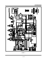
4. The conveyor belt is driven by a closed loop
D.C. drive system consisting of a 130 VDC moĆ
tor (15), a #2 Hall effect pickup (16), a DC
speed control board (17) and the DAC located
in the cooking computer. The motor speed varĆ
ies based on the time programmed into the
cooking computer. If time is programmed, a
voltage from .3 to 3.8 is applied to the DC
speed control board. The output voltage meaĆ
sured at terminals A1 and A2 varies from 20 to
130 VDC based on the DAC voltage applied to
the board or the time programmed into the
computer.
NOTE: The DAC receives 20 VDC from the
speed control board. The DAC returns
a portion of the voltage (between .3
and 3.8 VDC). The amount of voltage is
dependent on the time programmed
into the computer.
NOTE: This type of system does sense the
weight of the product and will not slow
down if the belt is fully loaded.
NOTE: The control voltage is supplied by a
240/120 step down transformer (18). The
transformer is located in the control
compartment.
Summary of Contents for MT2136 Series
Page 4: ...INTRODUCTION CHAPTER 1 ...
Page 15: ...MT2136 1 11 35 30 35 29 39 28 38 33 34 31 37 36 26 27 32 EXTERIOR COMPONENTS FIGURE 3 ...
Page 17: ...MT2136 1 13 CE GAS BURNER COMPONENTS Control Box not Shown 16 17 FIGURE 5 ...
Page 19: ...MT2136 1 15 This page intentionally left blank ...
Page 20: ...ASSEMBLY CHAPTER 2 ...
Page 23: ...MT2136 2 3 This page intentionally left blank ...
Page 24: ...OPERATION CHAPTER 3 ...
Page 49: ...MT2136 3 25 16 17 18 19 20 21 12 13 13 13 4 7 15 3 2 1 14 8 9 10 6 11 5 5 FIGURE 4 ...
Page 50: ...OPERATION 3 26 16 17 20 19 18 15 3 12 13 13 13 4 14 7 1 2 8 9 10 6 11 5 5 FIGURE 5 ...
Page 53: ...MT2136 3 29 1 17 3 2 4 16 16 16 15 21 5 13 14 14 10 18 19 6 7 8 20 9 12 11 FIGURE 8 ...
Page 54: ...OPERATION 3 30 1 18 16 16 16 16 17 15 22 5 3 2 4 13 10 19 20 6 7 8 21 9 12 11 14 14 FIGURE 9 ...
Page 55: ...MT2136 3 31 1 21 21 21 17 16 22 18 20 19 14 3 2 4 11 6 13 12 15 10 7 8 9 5 FIGURE 10 ...
Page 56: ...OPERATION 3 32 1 8 8 8 8 6 7 16 15 17 18 3 2 4 11 5 9 9 12 13 14 FIGURE 11 ...
Page 57: ...MT2136 3 33 1 6 9 8 19 22 21 7 16 17 2 3 4 18 5 10 14 20 12 11 13 15 25 25 25 24 FIGURE 12 ...
Page 58: ...OPERATION 3 34 1 FIGURE 13 ...
Page 60: ...CALIBRATION AND ADJUSTMENT CHAPTER 4 ...
Page 77: ...MT2136 4 17 This page intentionally left blank ...
Page 78: ...TROUBLESHOOTING CHAPTER 5 ...
Page 86: ...TECHNICAL APPENDIX CHAPTER 6 ...

