


INSTALLATION
CB5A-021 page 8/24
RELIEF VALVES
A relief valve of a type, material and pressure rating
suitable to the installation, MUST be installed. The relief
valve shall be installed in the discharge line between the
compressor head and the first block valve.
Compressor operating against closed
valve can cause system component
failure, personal injury or property
damage.
Hazardous pressure
can cause serious
personal injury or
property damage
Since all systems differ in design, care must be taken to
ensure the relief valve is installed to safely vent away
from sources of ignition and personnel. This can be
accomplished by either orientation or a pipe away;
consult the Relief Valve manufacture for assistance.
Operation of the relief valve can release
explosive gas to the atmosphere
creating an explosion hazard, possibly
causing personal injury or death
Hazardous gases
can cause property
damage, personal
injury or death
Should the Relief Valve actuate, the cause MUST be
determined and corrected before continuing operations.
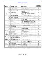
See the 'Troubleshooting' section.
Blackmer offers various relief valves for gas and
application compatibility:
Brass for LP-Gas service
Aluminum for anhydrous ammonia
Steel, A.S.M.E. code stamped for both services, and
other applications.
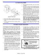
LIQUID TRAPS
Compressors handling gasses containing condensates
or other liquids MUST be protected from entry of the
liquid. Liquid can also enter the compressor from the
discharge piping, particularly if the piping slopes down
toward the compressor. To prevent liquid from entering
the compressor and causing major damage, it is
necessary to carefully consider the system design and
have strict procedures for operation.
NOTICE: Liquid in the compressor cylinder can
cause destruction of the compressor.
Blackmer offers a variety of liquid traps. The most
common variations include:
1. A non-code vessel fitted with a stainless steel float
which will shut off the intake line to the compressor
in the event of an excessive liquid level. A vacuum
breaking valve is provided on the liquid trap head in
case the trap closes and a vacuum develops
between the compressor and the trap. A manual
drain valve is provided.
2. The above trap is fitted with a port allowing the use
of an electric float switch which protects the
compressor by stopping the compressor when a high
liquid level is present in the liquid trap. The electric
float switch may be used with or without the
mechanical float described above.
3. For additional protection, a larger ASME code
stamped vessel is available. This liquid trap is
typically fitted with one or two electric float switches
for both a high liquid level shut down and alarm
signal, a relief valve, and a manual drain valve. This
type trap is needed if level gauges or automatic drain
systems are to be used.
4-WAY VALVES
Many liquefied gas compressors are used for both liquid
transfer and vapor recovery operations. An optional 4-
way valve is used to reverse the direction of flow through
the system when changing from liquid transfer to vapor
recovery. Both lubricated and non-lubricated models are
available. Lubricated models should be lubricated every
6 months.
TEMPERATURE SWITCHES
Excessive discharge temperature is a leading cause of
premature component failure and is often an early
warning sign of impending problems.
Optional temperature switches should be installed with a
thermowell as close to the compressor discharge as
possible. The switch should be set to actuate at a
temperature just above the maximum operating
temperature of the compressor.
ATEX compliant compressors
must
have a temperature
switch installed.
LOW OIL PRESSURE SWITCHES
Loss of crankcase oil pressure is a rare occurrence, but
can result in costly damage. An optional low oil pressure
switch set at about 15 psig (1 bar-g) may be installed to
shut down the compressor in the event of a lubrication
failure. A 10 second delay timer should be used to lock
the low oil pressure switch out during compressor
startup.
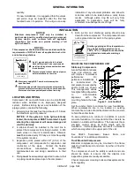
Figure 7 –
Typical Liquid Trap


