


OIL PUMP REPLACEMENT
CB5A-021 page 22/24
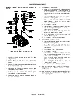
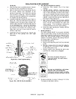
Figure 15 – Oil Pump
1. Remove the oil pump cover bolts and oil pump cover.
2. Remove the oil pump assembly, drive cone and
spring.
3. Clean and inspect parts for wear or damage, replace
as necessary.
4. Place the spring and the drive cone in the end of the
crankshaft.
5. Note the slot in the end of the crankshaft and the
drive tab on the back of the oil pump assembly.
Install the oil pump assembly into the bearing carrier
with the tab and slot aligned.
6. Note the groove around outer edge of the oil pump
assembly and the stop pin in the oil pump cover.
Position the oil pump cover and new gasket with the
pin in the oil pump groove, rotating the oil pump as
needed. The bolt hole positions ensure proper
orientation of the oil pump cover.
7. BY HAND, tighten the oil pump cover bolts while the
pump cover is held flush with the bearing carrier.
NOTICE: If by hand tightening, the oil pump
cover cannot be drawn flush with the bearing
carrier, the drive tab or the stop pin are
improperly aligned. DO NOT WRENCH TIGHTEN
OR THE OIL PUMP WILL BE DAMAGED.
8. Once the oil pump cover is secured by hand, the
bolts may be evenly tightened per Table 7 - "Bolt
Torque."
EXTENDED STORAGE PROCEDURES
If a compressor is not to be put into service for some time,
or if a compressor is to be taken out of service for an
extended period, care must be taken to protect the
compressor. The following steps must be taken for both
bare compressors and those already piped into a
system.
If proper storage procedures are not followed,
damage to the compressor may occur. Complete
compressor disassembly and replacement of rod
packing, bearings and other parts may be required.
1. Keep a written record storage procedures performed
– preferably on the unit itself.
2. Fill the crankcase with rust inhibiting oil. (New
compressors leave the factory without oil.) Squirt oil
on the piston rods and crossheads through the
nameplate opening. Loosen the V-belts to relieve the
load on the bearings. Rotate the compressor by
hand a few times to distribute the oil.
3. Plug all openings and purge the compressor with an
inert gas such as nitrogen or
dry
air at about 50 psig
(3.5 bar-g). This may be done at the factory if
requested. Leave the compressor pressurized to
prevent air or moisture from entering the unit.
Check the unit monthly and add additional purge gas
as needed.
NOTICE: Tag the unit with a warning that it is
pressurized.
4. If a purge gas is not available, fog oil into the
compressor suction while rotating the unit. Then
plug all openings to keep out moisture, insects, etc.
5. Turn the flywheel by hand a few revolutions once
a month to distribute the oil.
6. Store the unit under a plastic wrap on its wooden
shipping base up off the ground. If the unit was
boxed for export shipment, leave it in its box. An
indoor or covered storage area is preferable.
7.
Placing the Compressor back in service.
When the compressor is to be put in service, vent the
remaining purge gas and change the crankcase oil.
Follow the "Pre-Startup Checklist" and "Startup
Procedure" sections in this manual.
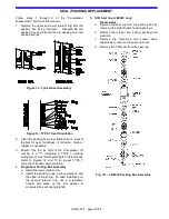
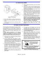
Figure 16 – Pressurized Compressor Tag
Compressor is pressurized with inert gas.
CAREFULLY bleed off gas BEFORE
attempting any service.
Hazardous pressure can
cause property damage,
serious personal injury
or death.


