


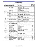


TROUBLESHOOTING
CB5A-021 page 23/24
PROBLEM
STEP
PROBABLE CAUSE
WHAT TO CHECK
IF PROBLEM
STILL EXISTS
GO TO STEP ...
Low
Transfer
Rate
1
4-Way Valve Leaking
(when equipped)
Lubricate with a stick lubricant compatible with
material being transferred.
2
2
Worn or Broken Piston Rings
Check condition of rings by restricting discharge
line. If pressure increases slowly, rings are
probably faulty.
3
3
Plugged Strainer
Clean screen as necessary.
4
4
Compressor Valve Faulty
Remove and inspect for broken or worn springs,
discs, or bodies.
5
5
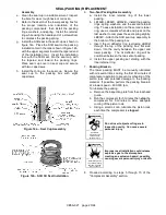
Liquid Relief Valves Need
Adjusting
Adjust per instructions in "Valve Replacement."
6
6
Compressor Drive Slipping
Tighten belts, check for sheared keys, loose keys
or loose flywheel.
7
7
Piping Improperly Designed or
Installed
Use proper pipe sizes.
8
No
Flow
8
Liquid Trap Full
Drain liquid trap through drain valve. Relieve
vacuum through bleeder valve on top of liquid trap.
9
9
Excess Flow Valves Slugged
Stop the compressor to let the excess flow open.
Installation of a valved bypass line between the
suction and discharge lines may be necessary.
6 & 7
Knocks or
Other
Noises
10
Loose Valves
Tighten valve hold-down screws.
11
11
Worn Internal Parts
Inspect through inspection plates and repair as
necessary.
4
No Oil
Pressure
12
Oil Pump Relief Valve Not Properly
Set.
Set oil pump relief valve.
13
13
Oil Pump Not Working
Check the Oil Pump drive tab or stop pin for
damage.
14
14
Low Oil Level
Check and fill as necessary
15
15
Dirty Inlet Strainer
Clean Inlet Strainer
Gas
Leaking
from
Crankcase
Breather
16
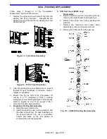
Faulty/Worn Packing
Replace Packing.
17
17
Piston Rod Scored
Replace crosshead assemblies and packing.
18
18
Improper Seal Arrangement
See "Seal Arrangements."
---
Relief
Valve
Actuates
19
Valve Closed Downstream of the
Compressor
Open Valve
20
20
Line Blockage Downstream of the
Compressor
Locate Blockage and Correct
---
Shake
or Vibration
21
Loose/Broken Mounting or Anchor
Bolts
See “Mounting the Compressor Unit“
22
22
Improper Mounting
Ensure base is supported full length. See
"Mounting the Compressor."
23
23
Improperly Aligned V-belt Sheaves See "V-Belt Drives"
24
24
Improperly Installed Flywheel
See "Compressor Flywheel"
25
25
Nonfunctioning Valves
Replace or repair valves.
---


