

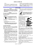


INSTALLATION
CB5A-021 page 6/24
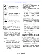
COMPRESSOR FLYWHEEL
Blackmer compressors are fitted with flywheels which
MUST be used regardless of the type of drive system
employed.
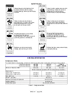
Failure to disconnect and lockout
electrical power or engine drive before
attempting maintenance can cause
severe personal injury or death
Hazardous
machinery can
cause serious
personal injury.
Flywheels must be properly installed and aligned:
1. Ensure that the mating surface between the hub and
flywheel are clean and dry – do not use a lubricant.
2. Install the hub and key on clean compressor shaft,
flange end first.
3. Tighten the hub setscrew just enough to prevent it
from sliding on the shaft – do not overtighten.
4. Place the flywheel on the hub and loosely thread the
capscrews with lockwashers into the assembly. Do
not use lubricant on the capscrews.
5. Tighten all capscrews evenly and progressively in
rotation to the torque value in Table 4. There must
be a gap between the hub flange and the flywheel
with installation is complete.
Do not over-torque.
Do not attempt to close gap between hub flange
and flywheel.
Hub
Size
Capscrew
Size
Torque
ft-lbs. (Nm)
SF
3/8 – 16
30 (40.7)
E
1/2 - 13
60 (81)
F
9/16 – 12
75 (101)
Table 4 – Flywheel Hub Torque Values
6. Ensure that the radial and axial runout values at the
rim do not exceed the following values:
Radial O.D. Runout: 0.016 in. (0.4046 mm)
Axial Rim Runout: 0.021 in. (0.5334 mm)
7. Ensure that the compressor flywheel guard is
properly installed before operation. The guard must
not contact moving parts.
Flywheel guard contact with moving
parts may be a source
of ignition in explosive atmospheres
causing severe personal injury or death
Hazardous gases
can cause property
damage, personal
injury or death
V-BELT DRIVES
Most Blackmer compressors are driven via V-belts which
must be properly aligned and tensioned.
Failure to disconnect and lockout
electrical power or engine drive before
attempting maintenance can cause
severe personal injury or death
Hazardous
machinery can
cause serious
personal injury.
1. Lay a straight edge along the face of the motor
sheave and compressor flywheel.
2. Adjust either as needed to provide alignment.
3. Tighten the V-belts such that they are taut, but not
overly tight. Moderate thumb pressure should
deflect each belt about 1/4 – 3/8 in. (6 – 10 mm).
Consult your V-belt supplier for specific values.
4. Check the belt tension after 24 - 48 hours run-in.
Recheck the tension periodically, and tighten the
belts as required.
Caution should be used to avoid overtightening belts,
which can shorten bearing and belt life. Belts should be
inspected periodically for signs of excessive wear and
replaced if necessary.
Operation without guards in place can
cause serious personal injury, major
property damage or death.
Hazardous
machinery can
cause serious
personal injury.
PTO DRIVES
Truck mounted Compressors may be driven by the
power take-off through a jackshaft connected by
universal joints. The compressor must be fitted with an
optional extended crankshaft to use a PTO drive without
removing the flywheel. Proper PTO installation is
essential:
1. Compressor shaft and PTO shaft must be parallel.
2. The yokes at the end of the jackshaft must be
parallel and in phase.
3. The angle between two shafts must not exceed 15°.
4. An EVEN number of U-joints must be used.
5. PTO shafts MUST have guards installed.


