BLACKMER LB161B Installation, Operation And Maintenance Instructions Download Page 20

SEAL (PACKING) REPLACEMENT


CB5A-021    page 20/24


Assembly 

e.  Clean the seal cup in a suitable solvent.  Inspect 

the bore for wear, roughness, or corrosion. 

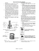
f.  Refer to the sketch of the lower packing box for 

the  proper  location  and  orientation  of  the 
packing  components,  then  install  the  packing 
rings, washers, and spring.  Install the retainer 
ring while using the handle end of a screwdriver 
to compress the packing spring. 

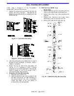
g.  Install the S3R seal in the seal cup as shown in 

figure 14a.  Place the S3R seal on the packing 
installation tool in the order shown in figure 14b, 
with the upper segment toward the tapered end 
of  the  installation  tool.    Insert  the  installation 
tool, with the S3R seal, into the seal cup, with 
the  tapered  end  toward  the  packing  rings.  
Place seal  cup  cover on seal  cup  and  secure 
with two capscrews 

h.  Install the O-ring on the seal cup.  Secure the 

seal  cup  to  the  packing  box  with  eight 
capscrews. 


Figure 14a – Seal Cup Assembly 


Figure 14b - S3R Oil Seal Installation 


6. 

Two-Seal Packing Box Assembly


a.  Install  the  inner  retainer  ring  of  the  lower 

packing. 

b.  LB162B, LB362C, LB602B – Install the packing 

rings, spring, washers, and the second retainer 
ring.  To ease installation on the second retainer 
ring, use a screwdriver handle and press on the 
last washer to compress the seal spring slightly. 
LB602C –Attach the S3R seal cup assembly to 
the bottom of the packing box. 

c.  Insert  the  oil  deflector  ring  (excluding  LB602) 

through  the  top  of  the  packing  box,  flat  side 
down,  into  the  cavity  between  the  upper  and 
lower  packing.    The  oil  deflector  ring  will  be 
positioned between the two sets of packing.  

d.  Install  the  upper  packing  set  starting  with  the 

inner retainer ring. 
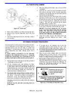
7. 

Packing Break-in


The  lower  packing  MUST  be  manually  lubricated 
with oil several times during the first 60 minutes of 
compressor operation to prevent overheating of the 
piston  rods  and  potential  damage  to  the  packing 
material.  If possible, perform the packing break-in 
at a lower speed – 400-500 rpm.  


To lubricate the packing: 
a.  Remove the inspection plate from the crosshead 

guide. 

b.  Run the compressor for 5 minutes then 

stop

 the 

compressor  for  5  minutes  to  allow  adequate 
cooling of the piston rods. 

c.  Using a small oil can,  lubricate the piston rods 

each time the compressor is 

stopped


Do not insert objects or fingers in 
inspection cavity.  Can cause severe 
personal injury 


Hazardous 

machinery can 

cause serious 

personal injury. 


Improper seal installation could release 
explosive gas to the atmosphere 
creating an explosion hazard, possibly 
causing severe personal injury or death. 


Hazardous gases 

can cause property 

damage, personal 

injury or death 

 
8.  Proceed  according  to  steps  5  through  15  of  the 

"Compressor Assembly" section. 


Summary of Contents for LB161B

Page 1: ...ALERT SYMBOL When you see this symbol on the product or in the manual look for one of the following signal words and be alert to the potential for personal injury or property damage Warns of hazards...

Page 2: ...luid or pressure containment components during compressor operation can cause serious personal injury death or major property damage Hazardous or toxic fluids can cause serious injury Hazardous pressu...

Page 3: ...EPLATE DATA A nameplate is attached to the side of all Blackmer compressors showing the Model No I D No and Serial No These numbers should be available when information or parts are needed for a parti...

Page 4: ...IMIZING COMPRESSOR LIFE Life of critical compressor components such as piston rings valves and packing will vary considerably with each application installation and operating procedures Premature fail...

Page 5: ...Strainers must be cleaned every 180 days or more frequently if the system requires 3 Expansion joints placed within 36 0 9 m of the compressor will compensate for expansion and contraction of the pip...

Page 6: ...e of ignition in explosive atmospheres causing severe personal injury or death Hazardous gases can cause property damage personal injury or death V BELT DRIVES Most Blackmer compressors are driven via...

Page 7: ...INSTALLATION CB5A 021 page 7 24 Figure 4 Liquid Transfer Flow Schematic Figure 5 Vapor Recovery Flow Schematic Figure 6 Typical Liquefied Gas Transfer Compressor...

Page 8: ...h will shut off the intake line to the compressor in the event of an excessive liquid level A vacuum breaking valve is provided on the liquid trap head in case the trap closes and a vacuum develops be...

Page 9: ...or death 2 Re check the system piping and the piping supports to ensure that no piping loads are being placed on the compressor Discharge piping surface temperatures may be hot during operation over...

Page 10: ...ge personal injury or death The oil pump on these models will operate in either direction of crankshaft rotation 2 Verify that the suction and discharge pressures are within the expected ranges Operat...

Page 11: ...injury Hazardous pressure can cause serious personal injury or property damage Explosive gas can cause property damage personal injury or death Extreme heat can cause personal injury or property damag...

Page 12: ...s Internal Snap Ring Pliers Seal Replacement Feeler gauges or Depth Micrometer Piston Clearance Screwdriver Flat Blade Nameplate screws Packing Installation Pliers Rubber Mallet Arbor Press Wrist Pin...

Page 13: ...ng the oil bring the compressor up to normal operating temperature Remove the crankcase drain plug and drain the oil into an adequately sized container Remove the oil pickup screen and clean in a suit...

Page 14: ...and cylinder O rings from the crosshead guide or distance piece 6 Packing Box Removal a Using an adjustable spanner wrench remove the packing box hold down rings Replace the nylon locking inserts in...

Page 15: ...the bearing with grease g Set the top of the connecting rod over the crankshaft journal Replace the connecting rod cap with the dots on the connecting rod and cap on the same side h Start the nuts on...

Page 16: ...e threading the piston clockwise onto the rod Tighten with the 3 adjustable spanner wrench d Follow this same procedure for the second piston e Rotate the crankshaft by hand a number of times to verif...

Page 17: ...rop the liquid relief ball and spring into the head interior 4 Discharge valve Remove the discharge valve cage valve assembly and gasket 5 Inspect the valve for wear or breakage 6 Ensure that the old...

Page 18: ...e the valve hold down screw is removed from the cover plate then place the cover plate and new O ring in position f Install the valve cover plate capscrews and tighten per Table 7 Bolt Torque g Instal...

Page 19: ...o Figures 12 and 13 for proper TYPE 1 component location and orientation 4 Single Seal Packing Box Assembly a Install the lower retainer ring b Install the packing rings spring washers and the upper r...

Page 20: ...last washer to compress the seal spring slightly LB602C Attach the S3R seal cup assembly to the bottom of the packing box c Insert the oil deflector ring excluding LB602 through the top of the packin...

Page 21: ...bearing cone onto each end of the crankshaft with the tapered end outward The bearing race should rest against the shoulder on the crankshaft e Lubricate the bearings with grease 8 Install the cranksh...

Page 22: ...age to the compressor may occur Complete compressor disassembly and replacement of rod packing bearings and other parts may be required 1 Keep a written record storage procedures performed preferably...

Page 23: ...lved bypass line between the suction and discharge lines may be necessary 6 7 Knocks or Other Noises 10 Loose Valves Tighten valve hold down screws 11 11 Worn Internal Parts Inspect through inspection...

Page 24: ...CB5A 021 page 24 24 1809 Century Avenue Grand Rapids Michigan 49503 U S A 616 241 1611 Fax 616 241 3752 www blackmer com...

Reviews: