


VALVE REPLACEMENT
CB5A-021 page 17/24
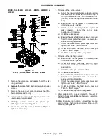
Figure 9 - Valve Location
Suction and discharge valves MUST be installed in the
correct cylinder head locations. See Figure 9.
The valves may be removed without removing the
cylinder head from the cylinder. Be sure to remove and
replace the valve gaskets.
Failure to install compressor valves
properly can lead to component failure,
personal injury or property damage.
Hazardous pressure
can cause serious
personal injury or
property damage
Failure to install compressor valves
properly can result in leakage of
explosive gas creating an explosion
hazard, possibly causing severe
personal injury or death.
Hazardous gases
can cause property
damage, personal
injury or death
Failure to install compressor valves
properly can result in extreme
discharge temperatures. This could be
an ignition source in the presence of
explosive gas possibly causing severe
personal injury or death.
Hazardous gases
can cause property
damage, personal
injury or death
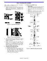
MODELS LB161B or LB162B
- see Figure 10.
1. Remove the valve cap and O-ring from the valve
being serviced.
2. Remove the valve hold down screw with a spanner
wrench, such as Blackmer PN 790535.
3. Suction valve - Remove the liquid relief valve body,
valve assembly and gasket. DO NOT drop the liquid
relief ball and spring into the head interior.
4. Discharge valve - Remove the discharge valve cage,
valve assembly and gasket.
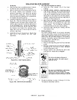
5. Inspect the valve for wear or breakage.
6. Ensure that the old gasket is removed, then install a
new valve gasket.
7. To reinstall the suction valves:
a. Install the valve assembly in the cylinder head.
Ensure the correct orientation and location of the
valve.
b. Center the liquid relief body on the valve
assembly.
c. Install the hold down screw and tighten per
Table 7 - "Bolt Torque."
d. Drop the liquid relief ball and the liquid relief
spring into the opening of the liquid relief body.
e. Insert the liquid relief adjusting screw and adjust
clockwise until the top of the screw is
approximately 3/8" (9.5 mm) above the top of the
liquid relief body. Add the locknut and tighten
securely.
8. To reinstall the discharge valves:
a. Install the valve assembly in the cylinder head.
Verify the correct valve orientation and location.
b. Center the valve cage on the valve assembly.
c. Install the hold down screw and tighten per
Table 7 - "Bolt Torque."
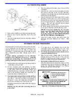
9. Install the valve cap and O-ring. A little oil or grease
on the O-ring will help hold it in place during
installation.
10. After replacing the valves, rotate the flywheel by
hand to check for interference between the pistons
and the valves.
11. After 60 minutes running time, remove the valve cap
and retorque the hold down screw. Replace the
valve cap and O-ring.
Figure 10 - LB161 or LB162 Valves


