


COMPRESSOR DISASSEMBLY
CB5A-021 page 15/24
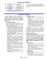
Compressor
Model
Bushing I.D.
Inches (mm)
LB161B, LB162B
LB361B, LB362C
0.8753 to 0.8756
(22.233 to 22.240)
LB601B, LB602C,
LB602B
1.2511 to 1.2514
(31.778 to 31.786)
Table 10 - Wrist Pin Bushing Dimensions
12. To replace the crankshaft bearings, the crankcase
must be disassembled, and the crankshaft removed.
Refer to the "Bearing Replacement" section of this
manual.
COMPRESSOR ASSEMBLY
Compressor assembly is generally the opposite of
compressor disassembly. Before reassembling, clean
each part thoroughly. Check all machined surfaces for
burrs or roughness, and file lightly if necessary.
Replace
any O-rings or gaskets that are removed or disturbed
during service.
1.
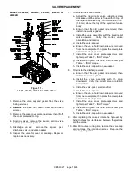
CRANKCASE ASSEMBLY
After replacing the crankshaft, bearing carrier, and
bearing cover plate, the connecting rod and
crosshead can be assembled in the crankcase. See
the "Bearing Replacement" section.
a. To attach the connecting rod to the crosshead
assembly, first coat the wrist pin, the wrist pin
bore in the crosshead assembly, and the wrist
pin bushing in the connecting rod with grease.
b. Start the wrist pin in the bore of the crosshead
assembly until the pin begins to project through
to the inside of the crosshead assembly. (Use
an arbor press if available.)
c. Slide the connecting rod up inside of the
crosshead assembly and align the bushing with
the wrist pin.
d. Install the wrist pin through the connecting rod
until it is centered in the crosshead assembly.
The wrist pin should be snug in the crosshead
assembly. The connecting rod should rotate
freely on the wrist pin, but should not be loose.
e. Dip the wrist pin plugs in grease and press them
against the ends of the wrist pin.
f. Place the bearing halves into each half of the
connecting rod, aligning the bearing tangs with
the slots in the connecting rod. Coat the bearing
with grease.
g. Set the top of the connecting rod over the
crankshaft journal. Replace the connecting rod
cap with the dots on the connecting rod and cap
on the same side.
h. Start the nuts on the connecting rod bolts and
torque per Table 7 - "Bolt Torque."
i. Follow this same procedure for the opposite
connecting rod.
2.
CROSSHEAD GUIDE
a. Place the crosshead guide gasket on top of the
crankcase.
b. Lubricate the inside bore of the crosshead guide
with light oil.
c. Set the crosshead guide over the piston rods
and crossheads, and slowly lower it against the
crankcase. Make certain that the crosshead
assemblies are started straight in the bores of
the crosshead guide to prevent binding when
lowering the crosshead guide into position.
d. Install the crosshead guide capscrews. DO NOT
tighten.
3. Fill the crankcase with oil. Refer to the "Crankcase
Lubrication" section. Squirt oil into the crankshaft,
roller bearings, crankshaft journals, and crosshead
assemblies to ensure proper lubrication at start up.
4. Attach the inspection plate and the inspection plate
gasket to the crankcase.
5.
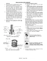
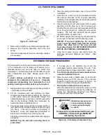
PACKING BOX ASSEMBLIES
Before installing the packing boxes into the
crosshead guide, inspect the piston rods for scoring
or roughness. Remove any burrs or sharp edges.
Lubricate the piston rods and packing box O-rings
with light oil.
Do not damage the packing when
starting it over the rod. Use of a Blackmer
packing installation tool is recommended, and
MUST be used on the LB602C.
(see ‘Tool List’
table).
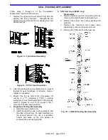
Single-Seal Models
a. Insert the packing box O-ring into the crosshead
guide.
b. Start the packing box assembly, short end down,
over the piston rod and into the counter-bored
hole of the crosshead guide.
c. Install the packing box retainer ring, with new
nylon locking inserts, and tighten securely.
d. Repeat the above steps for the remaining
packing box.
Double-Seal Models
a. Insert the lower packing box O-ring into the
crosshead guide.
b. Start the packing box assembly, short end down,
over the piston rod and into the crosshead guide.


