16
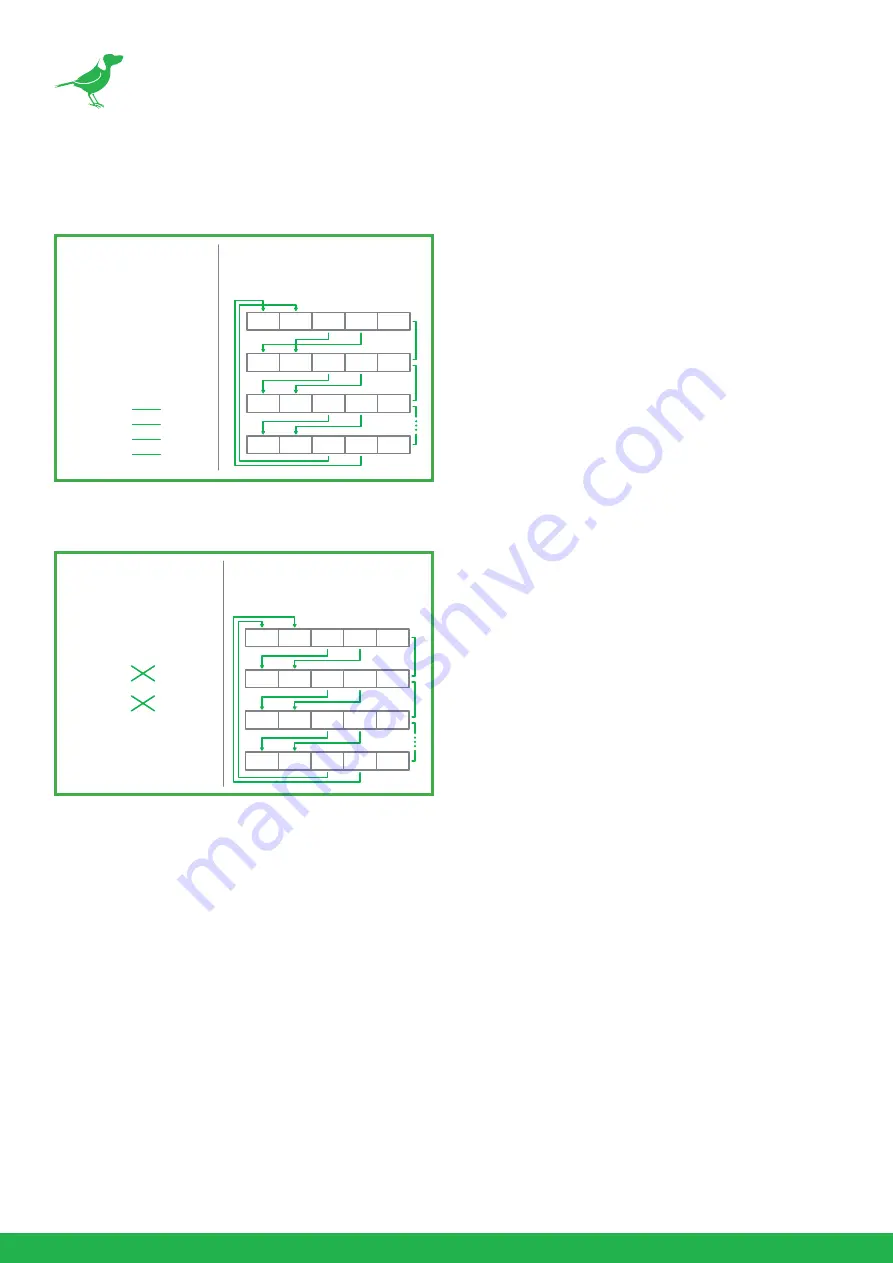
RS422 (VISCA) control connection diagram
SONY Keyboard RS422 Connection
VISCA (Non-Sony) Keyboard RS422 Connection
Setup Camera ID, Baud Rate and Control Protocol
In order for you to control the camera, the camera ID, baud rate and control protocol have to be set up in advance,
Baud rate and the camera ID setting on the camera have to be the same as baud rate and camera ID setting on the
system/control keyboard. The camera can auto detect the control method (VISCA or PELCO-D) - you only need
to set up the camera address and baud rate.
Connect the camera to a monitor. There is an initial setting page displaying on the screen for 5 seconds when the
camera is powered on. Shown is the factory default setting of the camera ID, baud rate and other information.
It is recommended that you capture an image of these settings for use in setting the control keyboard. Set the
keyboard or control system to match the camera ID, baud rate setting with the camera.
1.
Camera supports VISCA and PELCO-D protocols, protocol is detected automatically by the camera.
2.
Factory Default Setting: For both SDI and IP video, Baud Rate: 9600, Camera ID: 001, Pelco Protocol.
3.
When using RS485 Pelco-D, you can control up to 255 cameras. The camera ID from 001 to 255 has to be set.
Camera
(RS422)
4. TX +
3. TX –
2. RX +
1. RX –
Keyboard
1. ---
2. ---
3. ---
4. ---
5. GND
6. RXD IN –
7. RXD IN +
8. TXD IN –
9. TXD IN +
RS422 (VISCA)
Multiple Cameras Connection
(SONY Keyboard)
RX +
RX –
TX +
TX –
GND
RX +
RX –T
X +
TX –
GND
RX +
RX –T
X +
TX –
GND
RX +
RX –T
X +
TX –
GND
KEYBOARD
CAM 1
CAM 2
CAM 7
SONY Keyboard
RS422 Connection
Camera
(RS422)
4. TX +
3. TX –
2. RX +
1. RX –
Keyboard
1. GND
2. RXD IN –
3. RXD IN +
4. TXD IN –
5. TXD IN +
RS422 (VISCA)
Multiple Cameras Connection
(VISCA Keyboard)
RX +
RX –T
X +
TX –
GND
RX +
RX –T
X +
TX –
GND
RX +
RX –T
X +
TX –
GND
RX +
RX –T
X +
TX –
GND
KEYBOARD
CAM 1
CAM 2
CAM 7
VISCA Keyboard
Connection


