25
1. The tubing (5) is inserted in the cassette (6a) by sliding it through the groove.
2. The orange colored detent (5a) on the manifold side should mate with the notch in the back of the cassette.
3. The tubing should be longer on the chamber side than on the manifold side
4. When the tubing is secure, align the guide (6b) onto the pump bar and push the cassette until the lever (6c)
locks in place.
IMPORTANT
: Ensure all lines have the same tubing section lengths on the chamber side (after the manifold
(sections: 4, 5, 7)). These sections make up the “dead volume” of the line. For best results, it should be minimized
and kept as even as possible between lines.
7.6
Priming
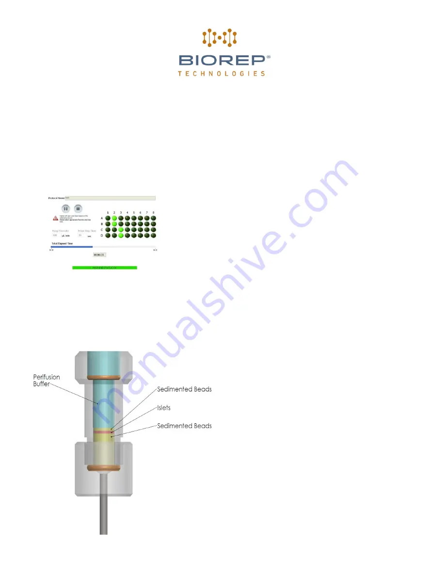
After the tubing is properly setup and the sources have been connected,
the system should be primed to remove any air in the system. This was
an involved process in previous versions of the perifusion machine that is
now performed automatically by pressing PLAY button. The machine
automatically performs the priming sequence depending on the active
protocol. You will be able to monitor the valve sequence followed by the
machine as it performs the priming. The progress will be displayed on
the bottom bar.
Figure 31: Priming page
7.7
Cell loading
When the system is completely primed and ready for the chamber to be attached:
Figure 32: Cell Loading
1. Place the bottom half of the assembled perifusion
chamber(s) on the rack with the bottom cap and
filter in place facing down
2.
Using a pipette, add 100µL of the bead and buffer
suspension to each chamber.
Please see
Appendix A for bead suspension preparation
instructions
3. When fluid starts dripping from the tubing, clamp
the tubing to retain the solution
4. Add the cell sample
5. Add a 25µL layer of the bead suspension
6. Fill remaining volume with buffer solution, making
sure to top off the chamber
7. Start the pump until solution starts dripping from
top caps. Flow rate is set at 50ml/min
8. Screw each chamber to its corresponding cap by
carefully turning the chamber body and quickly
remove the clamp
9. Place each chamber in their designated locations
in the machine rack and connect bottom tubing
section to designated dispensing nozzle
10. Stop the pump. All valves will close automatically
Summary of Contents for PERI-4.2
Page 30: ...30 AUC Area Under Curve...


