


ASSURANCE
GDS®
PPMX
USER
MANUAL
20
Pause
or
Stop
a
Running
Protocol
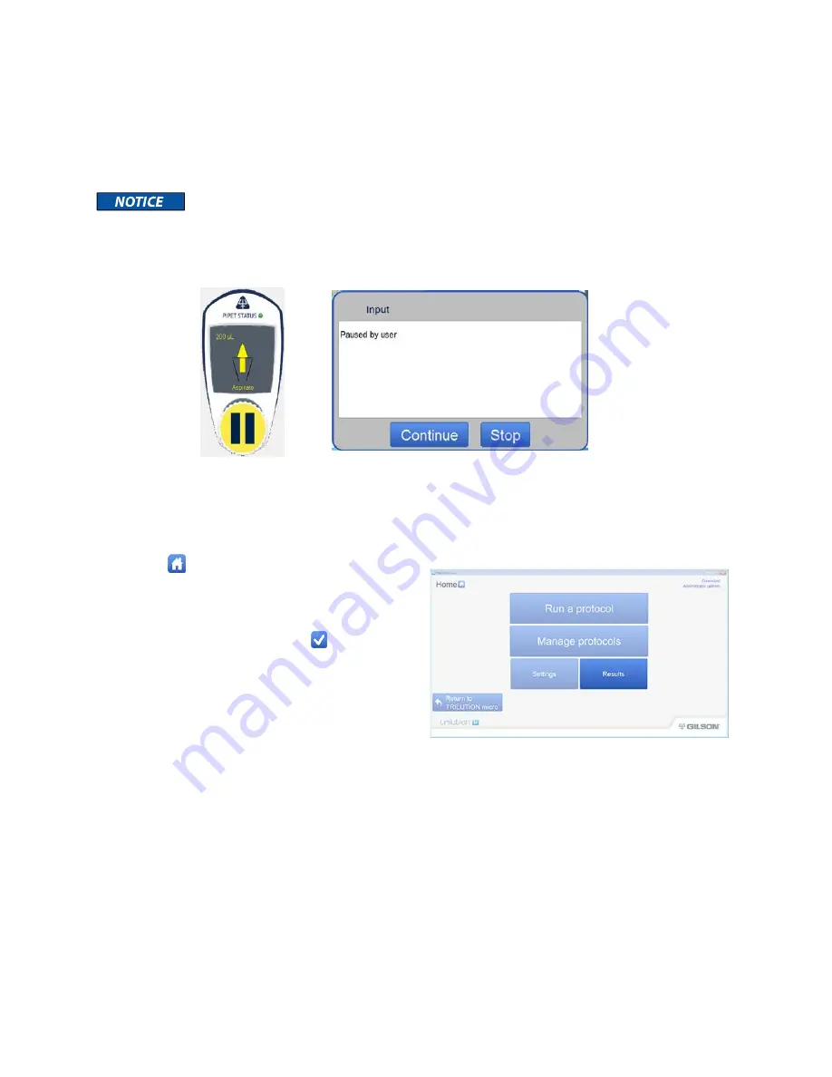
While
running
a
protocol
from
TRILUTION
micro,
click
or
touch
anywhere
on
the
PIPET
STATUS
image
to
pause
the
run.
The
run
will
stop
when
it
finishes
its
current
action.
The
protocol
run
timer
keeps
advancing
during
the
pause.
When
prompted,
select
Continue
to
resume
the
run,
or
Stop
to
end
the
run
and
view
the
results.
Do
not
pause
the
protocol
while
pipette
tips
are
being
picked
up
or
ejected.
To
stop
the
PPMX
in
an
emergency,
press
the
red
STOP
button
on
the
front
of
the
PPMX.
This
action
will
automatically
end
the
current
protocol
run.
View
Results
During
and
after
a
protocol
run,
information
is
available
about
reagent
dispense
volumes.
After
a
protocol
run,
results
for
that
run
are
automatically
displayed.
To
view
results:
1
Select
to
go
to
the
main
menu.
2
Select
Results
.
3
Select
a
protocol,
and
then
select
Results
.
4
Select
a
protocol
run,
and
then
select
View
.
Simulated
runs
are
identified
by
5
The
first
screen
displayed
when
viewing
results
is
the
Tray
view
screen.
The
colors
indicate
the
following
information:
Red
–
Negative
volume
Green
–
Volume
in
the
tube
or
well
Blue
–
Empty
tube
or
well
Pink
–
Tips
6
The
top
of
the
screen
shows
the
status,
the
name
of
the
protocol,
the
time
it
took
to
run
or
simulate
the
protocol
and
generate
the
results,
and
the
time
of
execution
for
the
last
step.
7
The
Volume
view
screen
displays
information
about
the
volume
in
the
selected
well
or
reservoir.
8
The
top
of
the
screen
shows
the
status,
the
name
of
the
protocol,
the
time
it
took
to
run
or
simulate
the
protocol
and
generate
the
results,
and
the
time
of
execution
for
the
last
step.
9
The
text
above
the
table
lists
the
bed
element
name,
the
well
location
and
label,
and
the
current
volume
in
the
well.
The
table
lists
the
actions
that
occurred
in
the
well
or
reservoir
in
the
following
order:
Initial
volume
(if
any)
Volume
added
and
the
source
of
the
volume
added
(bed
element
name
and
plate
index
or
reservoir
number)
Volume
removed
10
The
Steps
view
screen
displays
the
steps
that
were
run
in
the
protocol
in
the
order
of
execution.
11
The
top
of
the
screen
shows
the
status,
the
name
of
the
protocol,
the
time
it
took
to
run
or
simulate
the
protocol
and
generate
the
results,
and
the
time
of
execution
for
the
last
step.


