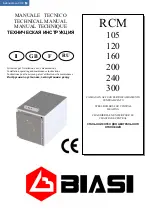


RCM
EDITION 09 / 2002
-
6
-
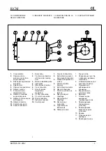
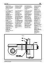
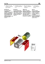
1.2 CARATTERISTICHE
TECNICHE GENERALI
I generatori di calore
BIASI
serie RCM sono generatori
in acciaio a combustione
pressurizzata che può
essere ottenuta sia con
combustibili liquidi che
gassosi.
Sono progettati per la
pressione massima di 4 bar
e sono del tipo a focolare
cieco cilindrico orizzontale
dimensionato per 2 giri di
fumo ad inversione di
fiamma; il terzo giro avviene
nel fascio tubiero.
All'interno del fascio tubiero
sono installati turbolatori,
costituiti da lame ondulate in
acciaio inossidabile che
aumentando la turbolenza
nel flusso di fumo,
migliorando lo scambio
termico e il rendimento del
generatore (superiore al
90%).
La porta anteriore è
normalmente predisposta
per il montaggio del
bruciatore previsto dal
cliente; al suo interno è
isolata con preformato
isolante/refrattario resistente
alle alte temperature
opportunamente sagomato
per convogliare verso il
fascio tubiero i fumi
provenienti dal focolare.
Le cerniere sono state
studiate per permettere
l’apertura della porta
anteriore indifferentemente
da destra o da sinistra.
Al di sopra della piastra di
fissaggio del bruciatore è
installato un manicotto con
spia in vetro pirex per
l'osservazione della fiamma
in camera di combustione.
Per raffreddare e mantenere
pulita la spia, essa è dotata
di attacco portagomma per il
collegamento alla presa
d'aria del bruciatore; lo
smontaggio temporaneo di
questo collegamento
permette la misura della
pressione in camera.
La camera a fumo posteriore
è imbullonata per consentire
la sua rimozione in
occasione di manutenzioni
straordinarie ed è dotata,
oltre che del raccordo fumi
1.2 GENERAL TECHNICAL
CHARACTERISTICS
BIASI
RCM steel boilers can
burn both liquid and gas
fuels. They are designed for
maximum 4 bar, and have
horizontal cylindrical
blank-back furnace with 2
smoke revolutions with
reverse flame and a third
revolution in the nest of
tubes.
Turbulators are installed in
the nest of tubes. These
consist of corrugated
stainless steel blades that
increase the turbulence of
the flow of smoke and
improve heat exchange and
boiler efficiency.
The front door is normally
designed to carry a burner
provided by the customer. It
is internally insulated with a
refractory/insulating casting
that resists high
temperatures and is
designed to convey smoke
coming from the furnace
towards the nest of tubes.
Hinges are designed to
permit the front door to open
either to the right or to the
left.
A sleeve is installed over the
burner fastening plate with a
Pyrex glass window to
observe the flame in the
combustion chamber.
The window has a hose
nipple connection that
connects to the burner's air
intake and functions to keep
the window clean and cool.
Temporary disconnection of
this connection permits the
pressure in the chamber to
be measured.
The rear smoke chamber is
bolted to permit removal
during extraordinary
maintenance. It also has, in
addition to the smoke fitting
for connection to the flue, a
removable inspection and
cleaning door and a
connection for draining off
any condensate.
The shell is insulated with
mineral wool mattresses.
External cladding is made of
internally insulated painted
steel sheet panels.
The support structure
consists of a sturdy
1.2 DESCRIPTION
La chambre de combustion
des chaudières
BIASI
RCM
est cylindrique, totalement
baignée et largement
dimensionnée pour
supprimer les contraintes
thermiques et de favoriser le
parcours de la flamme dans
le foyer borgne. Les
soudures sont toutes
exécutées en automatique
avec profils et bords
préalablement préparés.
La porte de la chaudière est
montée sur charnières.
L'ouverture est réglable à
droite ou à gauche pour les
modèles de 105 à 300 kW.
L'isolation haute
température de la porte est
conçue pour favoriser le
changement de direction
des produits de combustions
vers le faisceau tubulaire. La
chambre de combustion et
le faisceau tubulaire
présentent une grande
surface pour garantir un
excellant rendement.
Les tubes du faisceau sont
soudés aux plaques avant et
arrières sous "atmosphère
protégée".
Des chicanes en acier
inoxydable, insérées dans
les tubes ont pour rôle
d'augmenter la turbulence
des gaz de combustion et
d'accroître le coefficient de
transmission.
L'arrière du foyer de la
chaudière est équipé d'une
trappe de visite pour faciliter
l'entretien de la chaudière.
Les raccords de départ et de
retour chauffage sont placés
au-dessus de la chaudière
et sont équipés de brides et
de contre brides aux
dimensions normalisées.
Côté eau, des turbulateurs
favorisent l'échange
thermique évitant ainsi les
zones de surchauffe et de
stratification.
Les jaquettes des
chaudières sont en tôle
d'acier peinte, isolée à
l'intérieur (laine de verres en
couche comprimée).
Toutes les chaudières sont
essayées à la pression de
6,0 bars, pour une pression
1.2
ОБЩИЕ
ТЕХНИЧЕСКИЕ
ХАРАКТЕРИСТИКИ
Водогрейные
котлы
BIASI
серии
RCM
представляют
собой
стальные
котлы
с
герметичной
топкой
,
работающие
как
на
жидком
,
так
и
газообразном
топливе
.
Макс
.
рабочее
давление
4
бар
,
котлы
имеют
слепую
цилиндрическую
горизонтальную
топку
с
инверсией
пламени
,
размеры
которой
позволяют
уходящим
газам
совершать
два
оборота
,
третий
оборот
осуществляется
в
трубном
пучке
.
Внутри
трубного
пучка
установлены
спиральные
турбулизаторы
из
нержавеющей
стали
,
которые
,
увеличивая
турбулентность
в
потоке
дыма
,
улучшают
теплообмен
и
КПД
генератора
(
выше
90 %).
На
передней
дверце
устанавливается
горелка
,
выбранная
клиентом
;
внутри
она
покрыта
предварительно
отформованной
изоляцией
/
огнеупором
,
которая
особым
образом
профилирована
и
защищает
от
высоких
температур
;
она
направляет
в
трубный
пучок
уходящие
газы
из
топки
.
Шарниры
позволяют
открывать
переднюю
дверцу
как
налево
,
так
и
направо
.
Над
пластиной
для
закрепления
горелки
установлена
муфта
с
окошечком
из
стекла
пирекс
для
наблюдения
за
пламенем
в
камере
сгорания
.
Для
охлаждения
и
очистки
окошечко
оснащено
соединением
с
прокладкой
для
подключения
к
забору
воздуха
горелки
;
временный
демонтаж
этого
соединения
позволяет
измерить
давление
в
камере
.
Задняя
камера
дыма
привинчена
так
,
чтобы
обеспечить
ее
Summary of Contents for RCM 105
Page 2: ......


