


RCM
EDITION 09 / 2002
-
9
-
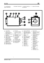
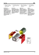
STRUMENTAZIONE ED
ACCESSORI
Le caldaie serie RCM sono
fornite complete dei seguenti
componenti:
-
pannello di comando e
controllo precablato
contenente:
termostati di regolazione
(pompa e bruciatore)
termostato di sicurezza a
riarmo manuale
termometro
interruttore di accensione
- pozzetto
per
termometro di prova
- piastra
forata
predisposta per
montaggio bruciatore
- materassino
in
fibra
ceramica per
tamponamento
boccaglio bruciatore
- serie
completa
di
turbolatori
- controflange
con
guarnizione e bulloni
(per gli attacchi flangiati)
scatola di cartone
contenente: materassino di
lana di vetro per isolamento
termico fasciame
pannellatura esterna
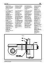
2. MONTAGGIO
2.1 MONTAGGIO CALDAIA
- Posizionare
la
caldaia
sul piano previsto per la
sua installazione che
deve essere piano,
consentire un appoggio
continuo della struttura
di sostegno e
dimensionato per il peso
della caldaia stessa
piena d’acqua
- effettuare
un’ispezione
generale (compreso il
getto refrattario della
porta) per controllare
che la caldaia non abbia
subito danni durante il
trasporto
-
La caldaia dev’essere
posta in modo che,
rispetto alle pareti del
locale caldaia siano
rispettate le distanze
minime previste dai
regolamenti vigenti e sia
in ogni caso assicurato
un agevole accesso per
NSTRUMENTS AND
ACCESSORIES
RCM boilers are supplied
with the following
components:
-
Prewired control panel
containing:
control thermostats
(pump and burner)
manually reset safety
thermostat
thermometer
main switch
-
test thermometer pocket
-
burner installation plate
-
ceramic fiber for
cladding the burner
nozzle
-
complete set of
turbulators
- counterflanges
with
gasket and bolts (for
flanged connections)
- cardboard
box
containing:
mineral wool for thermal
insulation
external casing
2. ASSEMBLY
2.1 BOILER ASSEMBLY
-
Position the boiler at its
installation site. This site
must be horizontal, give
uninterrupted support to
the boiler structure and
must be able to support
the weight of the boiler
when it is filled with
water.
- Perform
overall
inspection of the boiler
(including the door's
refractory casting) to
check that it has not
been damaged during
shipment.
-
The boiler must be
installed so that
distances from boiler
room walls comply with
the minimum distances
required by building
codes. Distances, in
any case, must
guarantee easy access
to the boiler for
APPAREILS DE
CONTROLE ET
ACCESSOIRES
Les chaudières RCM sont
équipées des composants
suivants :
-
Jaquette peinte, rapide
à monter après
l’installation du
calorifuge
- Double
isolation
thermique par matelas
en laine de verre
- Plaque
brûleur
- Chambre
de
combustion avec viseur
de flammes et trappe de
ramonage ou
d'inspection anti-chocs
-
Tableau de contrôle et
de régulation de la
chaudière qui
comprend:
un thermomètre
aquastates de
régulation (circulateur –
bruleur)
un aquastat de sécurité.
-
Série de chicanes en
acier inoxydable.
2. MONTAGE
2.1 MONTAGE DE LA
CHAUDIERE
-
La chaudière doit être
placée de façon à
respecter les distances
minimales visées par les
règlements en vigueur.
Notamment par rapport
aux murs du local de
chaufferie pour assurer
un accès aisé pour la
maintenance (Cf.
chapitre 3.8).
-
La chaudière doit être
posée sur un sol
horizontal et calculé en
fonction du poids de la
chaudière pleine d'eau.
-
Les tuyaux qui arrivent
aux raccords de la
chaudière doivent être
soutenus et disposés de
façon à ne créer aucun
effort sur les raccords
de la chaudière.
-
Les raccords des deux
tuyaux souples du
brûleur doivent être
ПРИБОРЫ
И
КОМПЛЕКТУЮЩИЕ
Котлы
серии
RCM
поставляются
со
следующими
компонентами
:
-
панель
управления
,
на
которой
расположены
::
регулирующие
термостаты
(
насоса
и
горелки
)
предохранительный
термостат
с
ручной
перезарядкой
термометр
выключатель
-
углубление
для
тестового
термометра
-
ответный
фланец
для
крепления
горелки
-
слой
керамического
волокна
для
тампонажа
сопла
горелки
-
турбулизаторы
-
контр
фланцы
с
прокладками
и
болтами
(
для
фланцевых
соединений
)
-
слой
стекловаты
для
изоляции
обшивки
-
внешние
панели
2.
МОНТАЖ
2.1
МОНТАЖ
КОТЛА
-
Установить
котел
на
предназначенную
для
него
ровную
площадку
,
обеспечить
постоянную
поддержку
несущей
конструкции
,
размеры
которой
должны
соответствовать
общему
весу
котла
-
Провести
общий
осмотр
(
включая
огнеупорное
покрытие
дверцы
),
для
проверки
,
что
котлу
не
был
нанесен
вред
во
при
транспортировке
.
-
Котел
должен
быть
установлен
с
соблюдением
мин
.
расстояния
до
стен
,
предусмотренного
действующими
правилами
;
доступ
к
котлу
должен
быть
легким
для
Summary of Contents for RCM 105
Page 2: ......


