Biasi RCM 105 Technical Manual Download Page 36


RCM


EDITION 09 / 2002 

 - 

34 

-


relativa data e tipo 
d’intervento eseguito.  


1. 

Tutte le operazioni 
devono essere eseguite 
a bruciatore fermo e 
caldaia a temperatura 
ambiente.  

2. 

Per evitare qualsiasi 
avviamento anche 
accidentale, si consiglia 
di asportare i fusibili 
della linea 
d’alimentazione elettrica 
o segnalare con un 
cartello il divieto 
d’azionamento 
dell'interruttore.  

3. 

Se la manutenzione è 
eseguita da più 
persone, concordare 
prima di iniziare i lavori, 
quale persona dovrà 
azionare gli interruttori.  

4. 

Chiudere la tubazione 
d’alimentazione del 
combustibile (gasolio, 
gas).  

5. 

Durante la pulizia, 
indossare abiti adatti, 
occhiali, guanti e 
maschera e seguire 
tutte le norme 
antinfortunistiche 
previste per lo specifico 
lavoro.  

6. 

Proteggere dalla 
polvere tutte le 
apparecchiature 
(quadro di controllo, 
quadro elettronico, 
guaina per le sonde, 
strumenti di controllo).  

7. 

Per la pulizia, usare 
scovoli aspiranti ed 
aspiratori.  

8. 

Quando si deve 
procedere al 
rimontaggio delle parti 
staccate per la pulizia, 
controllare attentamente 
le guarnizioni o, se 
necessario, sostituirle.  

9. 

Proteggere viti e dadi 
con grasso grafitato che 
faciliterà la successiva 
rimozione.  

10. 

Dopo aver predisposto 
la caldaia per un 
periodo di lunga 
inattività, apporre dei 
cartelli sugli interruttori 
e sulla caldaia che 
indicano con esattezza 
le operazioni da 
compiere prima del 
riavviamento.  

work that was performed.


1. 

All operations must be 
done with the burner off 
and the boiler at room 
temperature. 

2. 

We recommend, to 
prevent accidental start-
up, that you take out 
electric line fuses or put 
a warning card on the 
control switch. 

3. 

If maintenance is to be 
done by, several 
persons at once then 
before starting to work 
first agree on the 
person who is to 
actuate the control 
switches.  

4. 

Close the fuel supply 
pipeline (fuel oil, gas).  

5. 

Wear suitable 
garments, goggles, 
gloves and masks 
during cleaning.  
Comply with all the 
safety regulations 
specified for each type 
of job. 

6. 

Protect all instruments 
from dust and dirt 
(control board, 
electronic board, probe 
sheath, control gauges 
and instruments). 

7. 

Use aspirating flue 
brushes and vacuum 
cleaners for cleaning.  

8. 

Carefully inspect all 
seals when reinstalling 
parts that were 
detached for cleaning.  
Replace them if 
necessary. 

9. 

Protect screws and nuts 
with graphite grease to 
make it easier to 
remove them later.  

10. 

When the boiler has 
been shut down for an 
extended time period 
put message cards on 
the switches and the 
boiler that clearly 
specify procedures to 
perform prior to start-up. 

11. 

When re-starting the 
boiler, before igniting 
the burner, check that 
the boiler recirculation 
and heating system 
circulation pumps 
function properly. 


date de chaque visite, le 
type d’intervention et 
les opérations 
effectuées.


1. 

Toutes les opérations 
doivent être exécutées, 
lorsque le brûleur est 
arrêté et la chaudière à 
la température 
ambiante. 

2. 

Pour éviter tout 
démarrage, même 
fortuit, on conseille 
d’enlever les fusibles de 
la ligne d’alimentation 
électrique ou de 
signaler par un écriteau 
l’interdiction d'établir 
l'alimentation électrique.

3. 

Si la maintenance est 
exécutée par plusieurs 
personnes, avant de 
commencer les travaux, 
convenir qui devra 
actionner les 
interrupteurs. 

4. 

Fermer le conduit 
d’alimentation du 
combustible (fioul, gaz). 

5. 

Pendant le nettoyage, 
porter des vêtements 
adéquats, des lunettes, 
des gants et un masque 
et suivre toutes les 
normes contre les 
accidents prévus pour 
tout travail spécifique. 

6. 

Protéger contre la 
poussière tous les 
appareillages (tableau 
de contrôle, tableau 
électronique, gaine pour 
les sondes, instruments 
de contrôle). 

7. 

Pour le nettoyage, 
utiliser des écouvillons 
aspirants et des 
aspirateurs. 

8. 

Lorsqu’on doit effectuer 
le remontage des 
pièces détachées pour 
le nettoyage, contrôler 
attentivement les joints 
et, s’il le faut, les 
remplacer. 

9. 

Enduire les vis et les 
écrous avec de la 
graisse graphitée qui 
facilitera la dépose 
suivante. 

10. 

Après avoir préparé la 
chaudière pour une 
longue période 
d’inactivité, apposer des 
écriteaux sur les 
interrupteurs et sur la 

осмотр


с


соответствующей


датой


и


описанием


проведенных


работ


1. 

Все


операции


должны


проводиться


при


остановленной


горелке

при


температуре


котла


равной


температуре


помещения

2. 

Чтобы


избежать


случайного


запуска

рекомендуется


перенести


предохранители


линии


электрического


питания


или


поместить


карточку


с


запретом


трогать


выключатель

.  

3. 

Если


эксплуатация


проводится


несколькими


людьми

то


прежде


чем


начать


работу

они


должны


согласовать

кто


из


них


будет


управлять


выключателями

4. 

Перекрыть


питательный


трубопровод

 (

дизель

газ

).  

5. 

Во


время


очистки


надевать


спецодежду

очки

перчатки


и


маску


и


следовать


всем


предусмотренным


нормам


для


предотвращения


несчастных


случаев

6. 

Защитить


от


пыли


все


оборудование

 (

панель


управления

электронную


панель

кожух


зондов

приборы


контроля

).  

7. 

Для


очистки


использовать


всасывающие


ерши


и


аспираторы

8. 

Если


для


очистки


необходимо


демонтировать


прикрепленные


части

внимательно


проверить


прокладки


и


при


необходимости


их


заменить

9. 

Винты


и


гайки


защитить


слоем


графита

которые


облегчит


их


последующее


раскручивание

10. 

После


подготовки


котла


к


долгому


Summary of Contents for RCM 105

Page 1: ...R CENTRAL HEATING CHAUDIERES EN ENCIER POUR LE CHAUFFAGE CENTRAL MANUALE TECNICO TECHNICAL MANUAL MANUAL TECHNIQUE Istruzioni per l istallazione uso e manutenzione Installation operating and maintenan...

Page 2: ......

Page 3: ...e text that need to be emphasised WARNINGS or REQUIREMENTS This Installation Operating and Maintenance manual is applicable for all series RCM steel boilers designed to produce hot water at temperatur...

Page 4: ...d by the new owner Read the warnings and procedures with care before installing filling or starting up the system and before any maintenance The manual gives important information regarding system saf...

Page 5: ...eating plant 23 3 8 Connection to the smokestack 24 4 BURNER 4 1 Burner 26 5 SYSTEM START UP OPERATION AND MAINTENANCE 5 1 Filling the heating system 27 5 2 First start up and preliminary checks 27 5...

Page 6: ...1 1 RCM 1 DIMENSIONI DIMENSION DIMENSIONS RCM 105 120 160 200 240 300 A mm 805 805 855 855 940 940 B mm 870 870 920 920 1010 1010 C mm 1303 1303 1538 1538 1773 1773 D mm 725 725 775 775 860 860 E mm 8...

Page 7: ...on m 3 0 100 0 100 0 160 0 160 0 239 0 239 Portata gas naturale Natural gas flow rate D bit de gaz natural 8570 Kcal Nm3 Nm 3 h 11 5 13 2 17 5 21 9 26 1 32 7 Portata gasolio Fuel oil flow rate D bit d...

Page 8: ...oke coming from the furnace towards the nest of tubes Hinges are designed to permit the front door to open either to the right or to the left A sleeve is installed over the burner fastening plate with...

Page 9: ...di sostegno se non un piano di appoggio adeguatamente dimensionato I dati caratteristici della caldaia tipo pressione di funzionamento temperatura massima potenzialit N d omologazione matricola ecc so...

Page 10: ...strumenti 1 Boiler body 2 Front smoke chamber whit two side opening door 3 Burner installation plate 4 Light glass 5 Rear smoke chamber 6 Flue connection 7 Hole for smoke temperature measuring 8 Ch fl...

Page 11: ...with gasket and bolts for flanged connections cardboard box containing mineral wool for thermal insulation external casing 2 ASSEMBLY 2 1 BOILER ASSEMBLY Position the boiler at its installation site...

Page 12: ...r freely opening the burner support plate Ventilation must correctly furnish air to the burner Incoming fresh air from below and evacuation of stale air from the top part of the boiler room 2 2 BURNER...

Page 13: ...r if the hole for easy installation is oversized then the space between tube and insulation or rough cut edges must be carefully and totally filled with ceramic fibre after the burner is installed If...

Page 14: ...us s ni endommag s 3 Le num rotage indiqu sur la figure des composants suit l ordre de montage il est utilis pour toute la section 4 Ex cuter les diff rentes op rations en respectant l ordre indiqu a...

Page 15: ...boiler 7 remove the instrument control board cover and make electrical connections ATTENTION Run the board circulation pump and if present room thermostat connection supply cables through the cable g...

Page 16: ...golo anteriore 8 Reinstall the top panel on the instrument board cover IMPORTANT The name plate must be applied once the shell has been installed The name plate provided with this manual is installed...

Page 17: ...eating systems that use pressurised hot water with temperatures below 100 C WARNING RCM boilers have a maximum 5 bar operating pressure Consequently make sure that the hydraulic pressure measured down...

Page 18: ...t be insulated to prevent heat losses Leave pipelines exposed only where they require periodic inspection flanges expansion joint connections branches etc Insulation must be performed in accordance wi...

Page 19: ...esent in the smoke tubes and that no processing residue or foreign matter is present inside the furnace The system must also be furnished with all devices required by local codes regarding hot water b...

Page 20: ...s inside a fire tube boiler can cause breakage especially in thermally stressed zones in joints between fire tubes and the front tube plate for example The hardness of the water used to fill the heati...

Page 21: ...pianto elettrico deve essere realizzato in conformit alle norme della Legge 46 90 e suoi Decreti applicativi in particolare surface films It is also good practice to prevent acid corrosion to avoid us...

Page 22: ...that it conforms to the boiler s maximum absorbed power Also check that an efficient ground system is properly connected cable sizes are adequate and that there is a single pole isolating switch insta...

Page 23: ...nd cable is longer than the line and neutral cables so that it is the last to be disconnected in case the wires are torn off Refer to the wiring diagram in figure 4 to make connections This gives conn...

Page 24: ...itch SpC Circulation pump lamp TS Manually reset safety thermostat TP Circulation pump control thermostat Tr Thermometer T1 1 st stage boiler temperature thermostat T2 2 nd stage boiler temperature th...

Page 25: ...There must be at least 1 00 meters of free space above the boiler In addition the following regulations are required when using town gas systems with gas density less than 0 8 when compared to air Th...

Page 26: ...onnection to the boiler it must slope upward 5 min and if it is longer than 1 meter then it must be insulated in accordance with the safety regulations Insulation is necessary to prevent excessive coo...

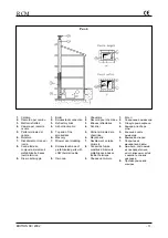
Page 27: ...1 Boiler 2 Smokestack connection 3 Refractory brick 4 Ash collection bin 5 Top end of the smokestack 6 Masonry 7 Mineral wool cladding 8 Smokestack made of prefabricated parts with LOW thermal inerti...

Page 28: ...gueur l g rement sup rieure l paisseur du rev tement r fractaire de fa on que la flamme se d veloppe l int rieur du foyer sans entrer en contact direct avec le r fractaire Le br leur doit tre choisi e...

Page 29: ...em with no sign of air 6 Check for air in the system by opening the vent valves in the upper part of the installation 7 Check pressure in the system on the pressure gauge 8 Check that the smokestack d...

Page 30: ...als are perfect and do not permit any smoke to leak out NOTE If there are small leaks around the hatchways these are eliminated by regulating the pressure on the gasket Do this by adjusting the nuts t...

Page 31: ...e in the boiler must be between 60 C and 80 C The difference in water temperature between heating system delivery and return must never exceed 20 C not even at the start and the return temperature doe...

Page 32: ...GENERAL BOILER OPERATING INFORMATION Boiler efficiency and durability depend on proper operation and maintenance as well as on correct installation The following guidelines must be complied with 1 As...

Page 33: ...requent topping up with water This could cause dangerous lime scale and corrosion in the boiler 8 Once a year check furnace cleaning Remove all scale and soot as necessary 9 Any gas leaks must be imme...

Page 34: ...Frequently check the pressure in the heating system as indicated on the pressure gauge When the heating system is cold the pressure must be as set by the installer depending on the height of the buil...

Page 35: ...re very hot and can cause burns Wait at least one hour after the burner has turned off before touching these components 6 To prevent accidents prevent extraneous persons from entering the boiler room...

Page 36: ...d for each type of job 6 Protect all instruments from dust and dirt control board electronic board probe sheath control gauges and instruments 7 Use aspirating flue brushes and vacuum cleaners for cle...

Page 37: ...60 C Important The first burner stage must be set up to guarantee this temperature limit Add antifreeze if necessary MAINTENANCE Boiler maintenance must be performed yearly at least and following ope...

Page 38: ...one dell impianto a persona fisica o giuridica in possesso dei requisiti previsti dalla normativa the retractory lining of the door and the ceramic fiber wool stuffed between the burner nozzle and the...

Page 39: ...bruciatore caldaia Burner boiler connection Raccord br leur chaudi re EN 267 Bruciatori monoblocco a polverizzatore Enbloc atomiser burners Br leurs monobloc pulv risation EN 303 Caldaie per riscalda...

Page 40: ...BIASI S p A 37135 VERONA Italy via Leopoldo Biasi 1 Tel 045 80 90 111 Fax 045 80 90 222 Internet http www biasi it Internet http www biasi ru RCM000 002...

Reviews: