Biasi RCM 105 Technical Manual Download Page 19


RCM


EDITION 09 / 2002 

 - 

17 

-


caldaia, l’impianto deve 
essere completato con i 
dispositivi previsti dalle 
specifiche tecniche 
applicative (Raccolta “R”) 
del D.M. 1 dicembre 1975 - 
Titolo II – riguardante le 
norme di sicurezza per 
apparecchi contenenti liquidi 
caldi sotto pressione 
emanato dall’I.S.P.E.S.L. :  

vaso di espansione 

(aperto o chiuso) 

tubo di sicurezza 

valvola o valvole di 

sicurezza 

- manometro 

con 

rubinetto e flangia per 
manometro di controllo 

pressostato di blocco 

II termostato di blocco o 

valvola di 
intercettazione del 
combustibile o valvola di 
scarico termico. 

 
3.3 TUBAZIONI DI 
MANDATA E RITORNO 
ACQUA DI 
RISCALDAMENTO 
 

1. 

Si consiglia di collegare 
la caldaia alla rete del 
riscaldamento con 
l'interposizione di due 
valvole 
d’intercettazione, che 
permettono di poter 
isolare la caldaia dal 
resto dell'impianto.  

2. 

Le eventuali valvole 
d’intercettazione 
devono essere disposte 
in modo tale che, in 
caso di chiusura, non 
esclude il tratto di 
tubazioni sul quale sono 
installati gli organi di 
sicurezza (pressostato, 
termostato di blocco, 
tubo di 
sicurezza/valvola di 
sicurezza); in ogni caso 
il tutto deve 
corrispondere a quanto 
stabilito dal D.M. 1-12-
75 Racc. R  I.S.P.E.S.L.  

3. 

In fase di progettazione 
e d’esecuzione 
dell'impianto, evitare 
accuratamente di creare 
punti nei quali possano 
ristagnare bolle d'aria. 
Se questa condizione 
non può essere 
rispettata, prevedere 
delle valvole 

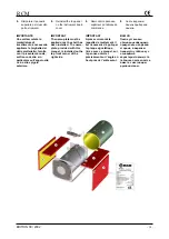
Moreover install the burner 
on the burner plate and 
connect the gas manifold or 
fasten the fuel hoses so that 
the door can be opened 
without impediments. 
Check that the turbulators 
are present in the smoke 
tubes and that no 
processing residue or 
foreign matter is present 
inside the furnace. 
The system must also be 
furnished with all devices 
required by local codes 
regarding hot water boilers. 


3.3 HEATING WATER 
DELIVERY AND RETURN 
PIPELINES 


1. 

Install two on/off valves 
when connecting the 
boiler to the heating 
system pipeline 
network.  This makes it 
possible to isolate the 
boiler from the rest of 
the heating system. 


2. 

On/off valves, when 
installed, must be 
placed so that they do 
not exclude safety 
components when they 
are activated (pressure 
switches, block 
thermostat, relief 
valve/relief pipeline, 
etc.).  The entire 
installation, in any case, 
must correspond to the 
suitable installation 
regulation  


3. 

Avoid creating points 
where air bubbles can 
form and stagnate when 
designing and installing 
the pipeline system.  If 
this cannot be avoided 
then install automatic air 
bleed valves or bleed 
pipelines that drain to 
the ground and that ave 

soupapes de sécurité  
est correctement 
effectué. 


3.3 TUYAUX DE DEPART 
ET DE RETOUR DU 
CIRCUIT DE CHAUFFAGE 


1. 

Il est conseillé de 
raccorder la chaudière 
au réseau du chauffage 
en intercalant deux 
vannes d’arrêt pour 
isoler la chaudière du 
reste de l’installation en 
cas de  besoin. 


2. 

Les vannes d’arrêt 
éventuelles doivent être 
disposées de façon 
qu’en cas de fermeture, 
le tronçon de tuyaux sur 
lequel sont installés les 
organes de sécurité 
(manostat, thermostat 
de blocage, tuyau de 
sécurité/soupape de 
sécurité) ne soit pas 
exclu; en tout état de 
cause, le tout doit être 
conforme aux 
règlements et normes 
en vigueur 


3. 

Au cours de la 
conception et de 
l’exécution de 
l’installation, éviter 
soigneusement de créer 
des contre-pentes où 
des bulles d’air puissent 
stagner. Prévoir des 
purgeurs d’air 
automatiques ou des 

8. 

Проверить


правильное


соединение


дренажа


предохранительных


клапанов


3.3 

ТРУБОПРОВОД


ПОДАЧИ


И


ВОЗВРАТА


ВОДЫ


ДЛЯ


ОТОПЛЕНИЯ


1. 

Рекомендуется


присоединять


котел


к


сети


отопления


с


использованием


двух


отсекающих


клапанов

которые


позволят


изолировать


котел


от


остальной


установки


2. 

Отсекающие


клапаны


должны


быть


расположены


так

чтобы


в


случае


закрытия


они


не


исключали


тот


отрезок


трубопровода

на


котором


установлены


предохранительные


компоненты


(

прессостат

термостат


блокировки

предохранительную


трубу

предохранительный


клапан


3. 


Во


время


проектирования


и


монтажа


установки


избегать


создания


точек

в


которых


могут


застаиваться


пузырьки


воздуха

Если


это


условие


не


соблюдается

необходимо


предусмотреть


два


автоматических


клапана


Summary of Contents for RCM 105

Page 1: ...R CENTRAL HEATING CHAUDIERES EN ENCIER POUR LE CHAUFFAGE CENTRAL MANUALE TECNICO TECHNICAL MANUAL MANUAL TECHNIQUE Istruzioni per l istallazione uso e manutenzione Installation operating and maintenan...

Page 2: ......

Page 3: ...e text that need to be emphasised WARNINGS or REQUIREMENTS This Installation Operating and Maintenance manual is applicable for all series RCM steel boilers designed to produce hot water at temperatur...

Page 4: ...d by the new owner Read the warnings and procedures with care before installing filling or starting up the system and before any maintenance The manual gives important information regarding system saf...

Page 5: ...eating plant 23 3 8 Connection to the smokestack 24 4 BURNER 4 1 Burner 26 5 SYSTEM START UP OPERATION AND MAINTENANCE 5 1 Filling the heating system 27 5 2 First start up and preliminary checks 27 5...

Page 6: ...1 1 RCM 1 DIMENSIONI DIMENSION DIMENSIONS RCM 105 120 160 200 240 300 A mm 805 805 855 855 940 940 B mm 870 870 920 920 1010 1010 C mm 1303 1303 1538 1538 1773 1773 D mm 725 725 775 775 860 860 E mm 8...

Page 7: ...on m 3 0 100 0 100 0 160 0 160 0 239 0 239 Portata gas naturale Natural gas flow rate D bit de gaz natural 8570 Kcal Nm3 Nm 3 h 11 5 13 2 17 5 21 9 26 1 32 7 Portata gasolio Fuel oil flow rate D bit d...

Page 8: ...oke coming from the furnace towards the nest of tubes Hinges are designed to permit the front door to open either to the right or to the left A sleeve is installed over the burner fastening plate with...

Page 9: ...di sostegno se non un piano di appoggio adeguatamente dimensionato I dati caratteristici della caldaia tipo pressione di funzionamento temperatura massima potenzialit N d omologazione matricola ecc so...

Page 10: ...strumenti 1 Boiler body 2 Front smoke chamber whit two side opening door 3 Burner installation plate 4 Light glass 5 Rear smoke chamber 6 Flue connection 7 Hole for smoke temperature measuring 8 Ch fl...

Page 11: ...with gasket and bolts for flanged connections cardboard box containing mineral wool for thermal insulation external casing 2 ASSEMBLY 2 1 BOILER ASSEMBLY Position the boiler at its installation site...

Page 12: ...r freely opening the burner support plate Ventilation must correctly furnish air to the burner Incoming fresh air from below and evacuation of stale air from the top part of the boiler room 2 2 BURNER...

Page 13: ...r if the hole for easy installation is oversized then the space between tube and insulation or rough cut edges must be carefully and totally filled with ceramic fibre after the burner is installed If...

Page 14: ...us s ni endommag s 3 Le num rotage indiqu sur la figure des composants suit l ordre de montage il est utilis pour toute la section 4 Ex cuter les diff rentes op rations en respectant l ordre indiqu a...

Page 15: ...boiler 7 remove the instrument control board cover and make electrical connections ATTENTION Run the board circulation pump and if present room thermostat connection supply cables through the cable g...

Page 16: ...golo anteriore 8 Reinstall the top panel on the instrument board cover IMPORTANT The name plate must be applied once the shell has been installed The name plate provided with this manual is installed...

Page 17: ...eating systems that use pressurised hot water with temperatures below 100 C WARNING RCM boilers have a maximum 5 bar operating pressure Consequently make sure that the hydraulic pressure measured down...

Page 18: ...t be insulated to prevent heat losses Leave pipelines exposed only where they require periodic inspection flanges expansion joint connections branches etc Insulation must be performed in accordance wi...

Page 19: ...esent in the smoke tubes and that no processing residue or foreign matter is present inside the furnace The system must also be furnished with all devices required by local codes regarding hot water b...

Page 20: ...s inside a fire tube boiler can cause breakage especially in thermally stressed zones in joints between fire tubes and the front tube plate for example The hardness of the water used to fill the heati...

Page 21: ...pianto elettrico deve essere realizzato in conformit alle norme della Legge 46 90 e suoi Decreti applicativi in particolare surface films It is also good practice to prevent acid corrosion to avoid us...

Page 22: ...that it conforms to the boiler s maximum absorbed power Also check that an efficient ground system is properly connected cable sizes are adequate and that there is a single pole isolating switch insta...

Page 23: ...nd cable is longer than the line and neutral cables so that it is the last to be disconnected in case the wires are torn off Refer to the wiring diagram in figure 4 to make connections This gives conn...

Page 24: ...itch SpC Circulation pump lamp TS Manually reset safety thermostat TP Circulation pump control thermostat Tr Thermometer T1 1 st stage boiler temperature thermostat T2 2 nd stage boiler temperature th...

Page 25: ...There must be at least 1 00 meters of free space above the boiler In addition the following regulations are required when using town gas systems with gas density less than 0 8 when compared to air Th...

Page 26: ...onnection to the boiler it must slope upward 5 min and if it is longer than 1 meter then it must be insulated in accordance with the safety regulations Insulation is necessary to prevent excessive coo...

Page 27: ...1 Boiler 2 Smokestack connection 3 Refractory brick 4 Ash collection bin 5 Top end of the smokestack 6 Masonry 7 Mineral wool cladding 8 Smokestack made of prefabricated parts with LOW thermal inerti...

Page 28: ...gueur l g rement sup rieure l paisseur du rev tement r fractaire de fa on que la flamme se d veloppe l int rieur du foyer sans entrer en contact direct avec le r fractaire Le br leur doit tre choisi e...

Page 29: ...em with no sign of air 6 Check for air in the system by opening the vent valves in the upper part of the installation 7 Check pressure in the system on the pressure gauge 8 Check that the smokestack d...

Page 30: ...als are perfect and do not permit any smoke to leak out NOTE If there are small leaks around the hatchways these are eliminated by regulating the pressure on the gasket Do this by adjusting the nuts t...

Page 31: ...e in the boiler must be between 60 C and 80 C The difference in water temperature between heating system delivery and return must never exceed 20 C not even at the start and the return temperature doe...

Page 32: ...GENERAL BOILER OPERATING INFORMATION Boiler efficiency and durability depend on proper operation and maintenance as well as on correct installation The following guidelines must be complied with 1 As...

Page 33: ...requent topping up with water This could cause dangerous lime scale and corrosion in the boiler 8 Once a year check furnace cleaning Remove all scale and soot as necessary 9 Any gas leaks must be imme...

Page 34: ...Frequently check the pressure in the heating system as indicated on the pressure gauge When the heating system is cold the pressure must be as set by the installer depending on the height of the buil...

Page 35: ...re very hot and can cause burns Wait at least one hour after the burner has turned off before touching these components 6 To prevent accidents prevent extraneous persons from entering the boiler room...

Page 36: ...d for each type of job 6 Protect all instruments from dust and dirt control board electronic board probe sheath control gauges and instruments 7 Use aspirating flue brushes and vacuum cleaners for cle...

Page 37: ...60 C Important The first burner stage must be set up to guarantee this temperature limit Add antifreeze if necessary MAINTENANCE Boiler maintenance must be performed yearly at least and following ope...

Page 38: ...one dell impianto a persona fisica o giuridica in possesso dei requisiti previsti dalla normativa the retractory lining of the door and the ceramic fiber wool stuffed between the burner nozzle and the...

Page 39: ...bruciatore caldaia Burner boiler connection Raccord br leur chaudi re EN 267 Bruciatori monoblocco a polverizzatore Enbloc atomiser burners Br leurs monobloc pulv risation EN 303 Caldaie per riscalda...

Page 40: ...BIASI S p A 37135 VERONA Italy via Leopoldo Biasi 1 Tel 045 80 90 111 Fax 045 80 90 222 Internet http www biasi it Internet http www biasi ru RCM000 002...

Reviews: