24
Robusta SC
WARNING!
IN ANY CASE DO NOT ADJUST WITH THE M10 NUTS AND BOLTS FOR
THE CONNECTION OF THE BASE PLATE AND THE WHEEL SUPPORT.
8)
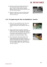
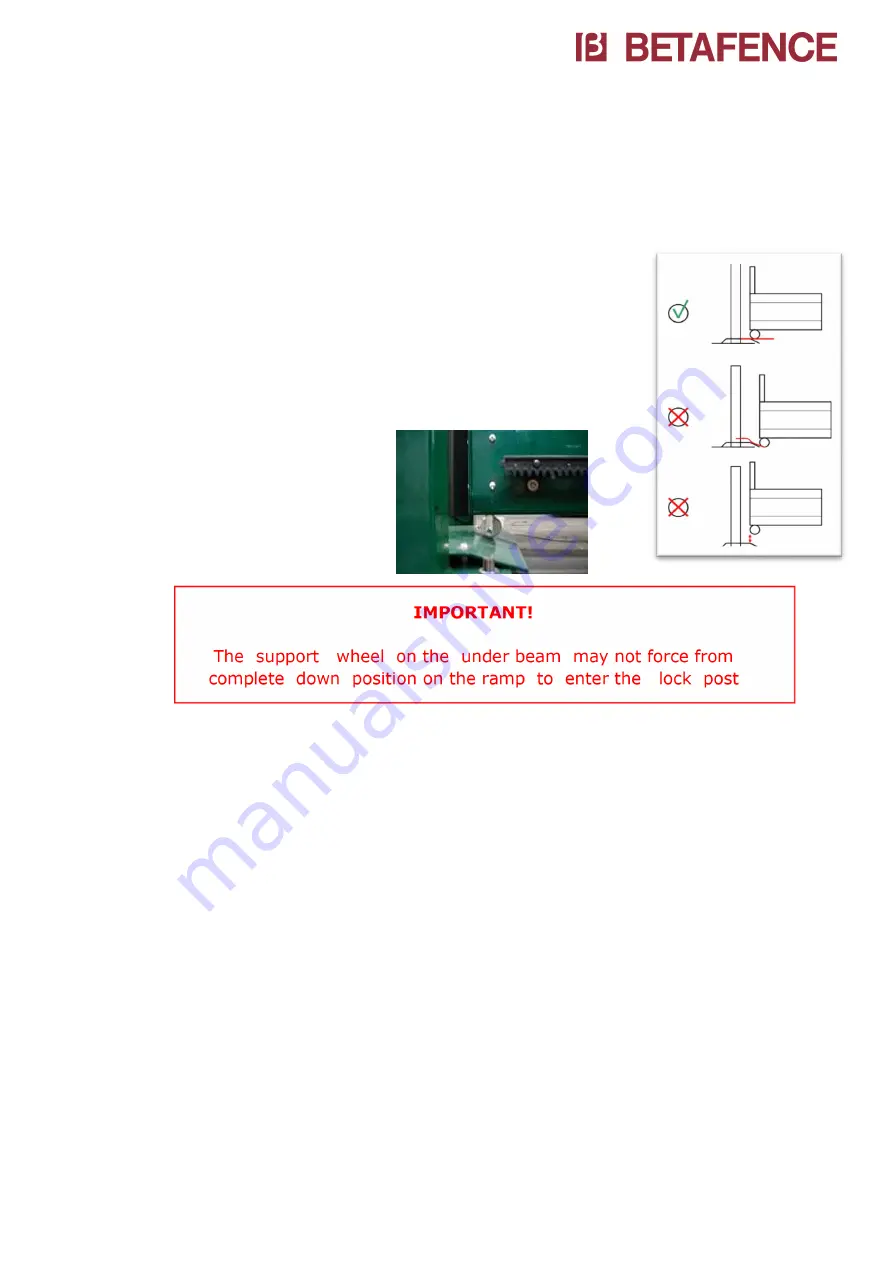
After alignment of the lock post and horizontal
leveling of the wing, adjust the height of the
lock post so that the support wheel under the
front of the under beam is slightly touching the
ramp (of the lock post) just below the
horizontal surface. Beware to keep the vertical
levels and the positioning in the catcher of the
lock post. The height adjustment is done with
the nuts of the ground anchors.
IMPORTANT!
The support wheel on the under beam may not force from
complete down position on the ramp to enter the lock post
9)
After full adjustment of the gate, tension up all nuts from the
ground anchors. Then cut the lengths of the ground anchors
1/2 cm above the nuts, and paint afterwards against
corrosion.
4.8.
Installation of the support roll:
Gates with a free passage more than 5m00 have a support roll for the wing in
open position. Install that roll on the foundation as described on the next
page:
1)
Correct adjustment of this roll is indispensable for a good
functioning of the Robusta® cantilever-sliding gate. The
adjustment is required as well for the correct height of the
support roll as for the perpendicular of the support roll
towards the under beam of the wing.
Summary of Contents for R2000
Page 1: ...1 Robusta SC Cantilever sliding gates Robusta SC Installation Manual ...
Page 11: ...11 Robusta SC 4 1 1 Automatic version right opening ...
Page 12: ...12 Robusta SC 4 1 2 Automatic version left opening ...
Page 13: ...13 Robusta SC 4 1 3 Motorizable version right opening ...
Page 14: ...14 Robusta SC 4 1 4 Motorizable version left opening ...
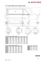
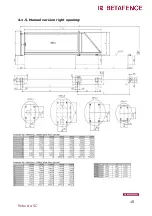
Page 15: ...15 Robusta SC 4 1 5 Manuel version right opening ...
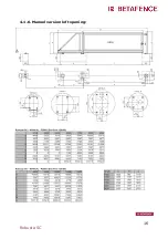
Page 16: ...16 Robusta SC 4 1 6 Manuel version left opening ...


