(EN)
GETTING START TO WORK
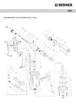
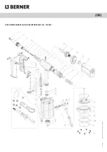
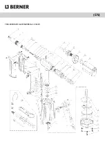
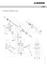
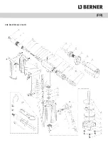
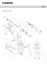
Please refer to the TOOL EXPLOSIVE ILLUSTRATION and the PARTS LIST in this manual in order to have a good understanding
of the tool parts described. The descriptions of the tool parts appear in this manual are in italics with the parts position num-
bers corresponding to the tool explosive illustration.
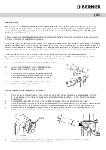
1) This pneumatic powered tool should be worked with compressed air supply. It is recommended to use the air hose with diameter
bigger than 8 mm;
2) To check the compressed air pressure within the specified range between 0,5Mpa and 0,7Mpa, and to connect the air hose adaptor
onto the tool air adaptor (#53). The air adaptor has its different versions in different countries and areas, normally the tools are equipped
with the correct version as default, in case the air adaptor does not apply in your air supply hose adaptor, contact the tool distributor(s);
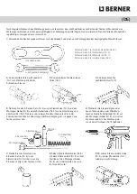
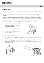
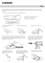
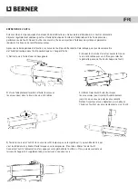
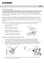
3) To change and use correct nosepiece (#1) according to the size of the rivet to be set. This tool is equipped with nosepieces
3,0/3,2mm, 4,0mm and 4,8/5,0mm (on the tool) in the tool kit. Follow the steps below to change the nosepiece (#1):
a)
To remove the air supply hose from air adaptor (#53).
b)
To use the wrench (in accessories pack) to remove
the nosepiece (#1) from the tool.
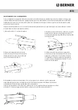
c)
To select the correct nosepiece in accessories pack
and screw on to the tool, using the wrench to fix it
firmly on the tool.
d)
To install the mandrel collector (#25, in accessories
pack) on the back of the tool.
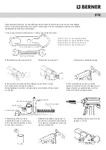
TOOL OPERATION FOR SETTING BLIND RIVET
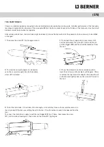
1)
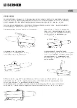
After start-up preparations, to put the rivet into the nosepiece with the rivet mandrel, and holding the tool to insert the rivet
into the pre-drilled hole of the work pieces where the work pieces needs to be fastened;
2)
To pull the tool trigger (#49) to set the blind rivet in its position on work piece;
3)
After setting the rivet, the rest mandrel of the rivets will be sucked into the mandrel collector (#25) automatically. Be sure to
empty the mandrel collector (#25) in time otherwise the tool can not release the mandrel properly.
4)
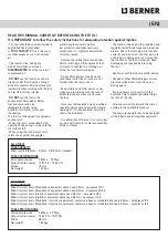
The air power of sucking the rest mandrel can be adjusted bigger or smaller, by the knob on back of the tool visible when the
mandrel collector removed:
5)
On the air adaptor hose (#54) equipped for this tool, there is a sliding switch for pause the air supply. To switch off for saving
air.
Knob
Summary of Contents for 414401
Page 7: ... DE EXPLOSIONSDARSTELLUNG DES WERKZEUGS Art 414401 ...
Page 14: ... EN TOOL EXPLOSIVE ILLUSTRATION Art 414401 ...
Page 15: ... EN DP 03 2021 Errors and technical changes reserved TOOL EXPLOSIVE ILLUSTRATION Art 414402 ...
Page 21: ... FR VUE ÉCLATÉE Art 414401 ...
Page 22: ... FR DP 03 2021 Irrtümer und technische Änderungen vorbehalten VUE ÉCLATÉE Art 414402 ...
Page 28: ... ES DIAGRAMA EXPLOSIONADO DE LA HERRAMIENTA Art 414401 ...
Page 29: ... ES DIAGRAMA EXPLOSIONADO DE LA HERRAMIENTA Art 414402 ...
Page 35: ... PT ILUSTRAÇÃO DETALHADA DA FERRAMENTA art 414401 ...
Page 36: ... PT ILUSTRAÇÃO DETALHADA DA FERRAMENTA art 414402 ...
Page 42: ... IT IMMAGINE ESPLOSA DELLO STRUMENTO Art 414401 ...
Page 43: ... IT IMMAGINE ESPLOSA DELLO STRUMENTO Art 414402 ...
Page 49: ... NL EXPLOSIETEKENING VAN HET GEREEDSCHAP Art 414401 ...
Page 56: ... DK EKSPLOSIV ILLUSTRATION AF VÆRKTØJET Art 414401 ...
Page 63: ... SE SPRÄNGSKISS ÖVER VERKTYGET art 414401 ...
Page 64: ... SE SPRÄNGSKISS ÖVER VERKTYGET art 414402 ...
Page 70: ... NO ILLUSTRASJON FOR VERKTØY Art 414401 ...
Page 71: ... NO ILLUSTRASJON FOR VERKTØY Art 414402 ...
Page 77: ... PL SCHEMAT NARZĘDZIA Art 414401 ...
Page 78: ... PL SCHEMAT NARZĘDZIA Art 414402 ...
Page 84: ... CZ ROZLOŽENÝ POHLED NA NÁSTROJ Art 414401 ...
Page 85: ... CZ ROZLOŽENÝ POHLED NA NÁSTROJ Art 414402 ...
Page 91: ... SK ROZPADOVÉ VYOBRAZENIE SÚČIASTOK NÁRADIA č výr 414401 ...
Page 92: ... SK ROZPADOVÉ VYOBRAZENIE SÚČIASTOK NÁRADIA č výr 414402 ...
Page 98: ... HU A SZERSZÁM ROBBANTOTT ÁBRÁJA Cikksz 414401 ...
Page 99: ... HU A SZERSZÁM ROBBANTOTT ÁBRÁJA Cikksz 414402 ...
Page 105: ... RO SCHEMĂ EXPLODATĂ A INSTRUMENTULUI art 414401 ...
Page 106: ... RO SCHEMĂ EXPLODATĂ A INSTRUMENTULUI art 414402 ...
Page 112: ... HR DETALJNA ILUSTRACIJA DIJELOVA artikl 414401 ...
Page 113: ... HR DETALJNA ILUSTRACIJA DIJELOVA artikl 414402 ...
Page 119: ... LV INSTRUMENTA DETALIZĒTA ILUSTRĀCIJA Izst 414401 ...
Page 120: ... LV INSTRUMENTA DETALIZĒTA ILUSTRĀCIJA Izst 414402 ...
Page 126: ... LT ĮRANKIO SCHEMA Art 414401 ...
Page 127: ... LT ĮRANKIO SCHEMA Art 414402 ...


