3 7
THIS IS AN UNCONTROLLED DOCUMENT.
THIS ELECTRONIC DOCUMENT MAY HAVE BEEN SUPERCEDED.
THE MOST CURRENT DOCUMENT INFORMATION IS AVAILABLE
FROM YOUR BELL HELICOPTER TEXTRON REPRESENTATIVE.
PRODUCT DATA
JANUARY 2003
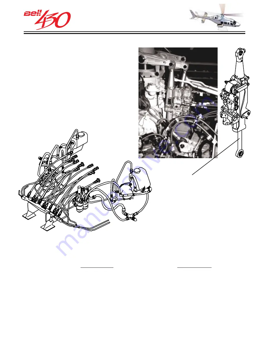
HYDRAULIC SYSTEM
T h e B e l l 4 3 0 h a s t w o c o m p l e t e l y
independent hydraulic systems, each with
its own reservoir, variable-delivery pump,
i n t e g r a t e d v a l v e a n d f i l t e r m o d u l e ,
t e m p e r a t u r e a n d p r e s s u r e m o n i t o r i n g
sensors, "Quick Disconnect" ground test
fittings, check valves, pressure and return
manifolds, and distribution network. Each
of the variable-delivery pumps is powered
by separate drive quills located on the left
a n d r i g h t f r e e w h e e l i n g u n i t s o f t h e
transmission.
The three dual hydraulic servo actuators in the cyclic and collective control system
are operated by both systems, which are designated PC 1 and PC 2. Additionally, the
directional control (ANTI-TORQUE) system servo actuator is powered by PC 1, and
provisions exist for PC 2 to power the optional wheel landing gear retraction mechanism.
Both systems operate continuously, but may be individually de-energized for functional
preflight system check. Two switches (HYD #1 & HYD#2), located on the overhead
console, control solenoid valves and are connected so that only one system at a time
can be de-energized.
The cyclic and collective servo actuators are mounted on the forward side of the
transmission in order to isolate them from any inputs caused by pylon motion.
The lower half of each servo is powered by PC 1, while the upper halves are powered
by PC 2. The nominal operating pressure of both systems is 10,342 kPa (1500 psi)
throughout the approved temperature range of -54° to +82°C (-65° to +180°F).
•EXAMPLE•
Summary of Contents for BELL 430
Page 1: ...Product Data ...


