


6
4.2
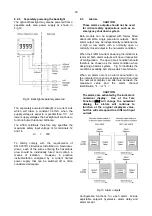
Remote indication
The BA304NG and the BA324NG may be driven
directly from a safe area instrument with a 4/20mA
output to provide a remote display within a Zone 2
hazardous area.
There are four design requirements:
1. The current flowing in the 4/20mA loop, must
not exceed 100mA in normal operation.
2.
Wiring must comply with Clause 9 of
EN60079-14
Electrical installation in
hazardous areas
.
3. The instrument enclosure must be fitted with
Ex n or Ex e certified glands, conduit fittings
or blanking plugs.
4. The safe area 4/20mA output from the safe
area instrument must be able to supply the
1.2V required to operate the indicator. This
increases to 5.0V if the indicator includes an
optional loop powered backlight. See 9.4.1
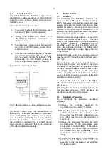
Fig 3 shows a typical application.
Fig 3 Remote indication in Zone 2 hazardous area
To strictly comply with the requirements of
EN 60079:14
Electrical Installation in Hazardous
Areas
, each of the wires entering the hazardous
area should be individually fused and contain a
means of isolation. However, in practice
instrumentation energised by a current limited
power supply or instrument that can be switched
off is often considered adequate.
5.
INSTALLATION
5.1
Location
The BA304NG and BA324NG indicators are
housed in robust IP66 glass reinforced polyester
(GRP) enclosures incorporating an armoured glass
window and stainless steel fittings making them
suitable for exterior mounting in most industrial
on-shore and off-shore Zone 2 installations. The
indicators should be positioned where the display
is not in continuous direct sunlight.
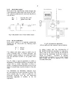
Field wiring terminals are located on the rear of the
indicator assembly as shown in Fig 5. If the field
wiring is to be terminated prior to the installation of
the indicator assembly, a back-box terminal
assembly, which includes a 4/20mA continuity
diode and additional terminals for linking cable
screens is available as an option. See section 9.5
of this manual.
Indicator terminals 2 and 4 are internally joined and
may be used for linking the return 4/20mA wire -
see Fig 2.
The instrument back-box is supplied with a
bonding plate that may be mounted on the inside
or outside of the enclosure to ensure electrical
continuity between the two conduit or cable entries.
The bonding plate includes an M4 earth stud
which, if the enclosure is not bolted to an earthed
post or structure, should be connected to the plant
potential equalising conductor.
An insulated M4 stud is provided in the bottom
right hand corner the back-box for interconnecting
cable screens.
Both indicators are surface mounting, but may be
pipe mounted using one of the accessory kit
described in section 9.4 of this manual.
5.2
Installation Procedure
Fig 4 illustrates the instrument installation
procedure.
A. Remove the indicator assembly by
unscrewing the four captive 'A' screws.
B. Mount the enclosure back-box on a flat
surface and secure with screws or bolts
through the four 'B' holes. Alternatively use
one of the pipe mounting kits described in
section 9.4.
C. Remove the temporary hole plug and install
an appropriate IP and temperature rated
cable gland or conduit fitting. If two entries
are required, the IP66 stopping plug should
be replaced with an appropriate IP and
temperature rated cable gland or conduit
fitting.
D. Connect the field wiring to the terminals as
shown in Fig 5. Replace the instrument
assembly on the back-box and evenly tighten
the four 'A' screws.


