background image

8

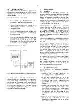
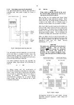
   Fig 6b Inserting scale card into the

 instrument assembly.

6.

CONFIGURATION AND CALIBRATION

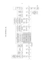
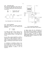
Both indicators are configured and calibrated via
the  four  front  panel  push  buttons.    All  the
configuration functions are contained in an easy to
use intuitive menu that is shown diagrammatically
in Fig 7.

Each menu function is summarised in section 6.1
and  includes  a  reference  to  more  detailed
information.    When  the  indicator  is  fitted  with
alarms additional functions are added to the menu
which are described in section 9.3

Throughout this manual push buttons are shown
as  

(

,  

)

,  

&

 or  

*

, and legends displayed by

the  indicator  are  shown  within  inverted  commas
e.g. 

CAL

 and 

ALr2

.

Access to the configuration menu is obtained by
operating  the  

(

 and  

)

 push  buttons

simultaneously.  If the indicator security code is set
to the default 

0000

 the first parameter 

FunC

 will be

displayed.  If a security code other than the default
code 

0000

 has already been entered, the indicator

will display 

CodE

.  Pressing the 

(

 button will clear

this prompt allowing each digit of the code to be
entered using the 

&

 and 

*

 push buttons and the

(

 button to move control to the next digit.  When

the  correct  four  digit  code  has  been  entered
pressing 

)

 will cause the first parameter 

FunC

 to

be displayed.   If the code is incorrect, or a button
is not pressed within twenty seconds, the indicator
will automatically return to the display mode. 

Once  within  the configuration  menu  the required
parameter can be reached by scrolling through the
menu using the 

&

 and 

*

 push buttons as shown

in Fig 7.       When returning to the display mode
following recalibration or a change to any function,
the  indicator  will  display  

dAtA

 followed  by  

5AVE

while the new information is stored in permanent
memory.

All  new  indicators  are  supplied  calibrated  as
requested at the time of ordering.  If calibration is
not requested, indicators will be supplied with the
following default configuration:

Default Configuration

BA304NG BA324NG

Access code  

CodE

0000

0000

Function  

FunC

Linear

Linear

Display at 4mA  

2ero

0.0

0.00

Display at 20mA  

5PAn

100.0

100.00

Resolution  

rE5n

1 digit

1 digit

Bargraph start  

BarLo

-----

0.00

Bargraph finish  

BarHi

-----

100.00

(

 button in display mode  

C--P

%

%

Tare  

tArE

Off

Off

Summary of Contents for BA304NG

Page 1: ...Issue 4 1st November 2017 BA304NG BA324NG Ex nA Ex tc loop powered field mounting indicators Issue 4...

Page 2: ...tor 7 3 Under and over range 7 4 Lineariser default configuration 8 Maintenance 8 1 Fault finding during commissioning 8 2 Fault finding after commissioning 8 3 Servicing 8 4 Routine maintenance 8 5 G...

Page 3: ...Notified Body Intertek Testing and Certification Ltd which has been used to confirm compliance with the European ATEX Directive 2014 34 EU For international applications both models have IECEx certifi...

Page 4: ...and dust certification This section of the instruction manual describes ATEX gas certification ATEX dust certification is described in Appendix 1 and IECEx approvals are described in Appendix 2 3 1 A...

Page 5: ...to display the measured variable or control signal in engineering units The indicators are transparent to HART signals There are four design requirements 1 The current flowing in the 4 20mA loop must...

Page 6: ...on the rear of the indicator assembly as shown in Fig 5 If the field wiring is to be terminated prior to the installation of the indicator assembly a back box terminal assembly which includes a 4 20m...

Page 7: ...ors are supplied with a printed scale card showing the requested units of measurement and tag information If this information is not supplied when the indicator is ordered a blank scale card will be f...

Page 8: ...r this prompt allowing each digit of the code to be entered using the and push buttons and the button to move control to the next digit When the correct four digit code has been entered pressing will...

Page 9: ...djusted without the need for an accurate input current or disconnection from the 4 20mA loop See section 6 6 bAr Bargraph format and calibration Only the BA324NG has a bargraph The bargraph may be con...

Page 10: ...10...

Page 11: ...not required it should be positioned beyond the most or least significant digit When positioned as required press the button to enter the selection and return to the configuration menu 6 5 Calibration...

Page 12: ...cator s digital display at which the bargraph starts is defined by the bArLo sub function which is selected by pressing the button followed by the button which will reveal the current indicator displa...

Page 13: ...ions shown in sections 6 0 and 7 3 To reset the indicator or lineariser select r5Et from the configuration menu and press the indicator will display one of the reset options ConF or LtAb ConF Resets t...

Page 14: ...ows direct calibration of the lineariser with an external current source and is the preferred method when traceability is required If the exact system non linearity is unknown this method also allows...

Page 15: ...15...

Page 16: ...ng break point 7 1 1 Example Adding break points to a new indicator When adding break points to a new indicator or to a lineariser following resetting to the factory defaults using the LtAb function d...

Page 17: ...n by pressing the button The corresponding indicator display at each of the break points can now be defined using the di5P sub function Using the and buttons select the di5P sub function and press whi...

Page 18: ...o risk of a flammable atmospjher being present If an indicator fails after it has been functioning correctly follow the procedure shown in section 8 1 If this does not reveal the cause of the fault it...

Page 19: ...haracters 5mm high 9 2 Display backlight The BA304NG and BA324NG loop powered indicators can be supplied with a factory fitted backlight that may be loop or separately powered When loop powered the ba...

Page 20: ...s an emergency shut down system Both models can be supplied with factory fitted dual solid state single pole alarm outputs Each alarm output may be independently conditioned as a high or low alarm wit...

Page 21: ...lication in which a BA304NG or BA324NG indicator is displaying the output from a 2 wire transmitter in Zone 2 Alarm 1 is switching a solenoid valve in Zone 2 and alarm 2 is switching a sounder located...

Page 22: ...tpoint The alarm is activated when the indicator display equals the setpoint See section 9 3 5 Hi Lo Alarm function Defines the alarm function as High or Low See section 9 3 6 no nC Normally open or n...

Page 23: ...23...

Page 24: ...e for fail safe operation both alarm outputs should be conditioned to be open in the alarm condition nC To check or change the alarm output status select no nC from the alarm configuration menu and pr...

Page 25: ...t having access to the indicator configuration menu Protection against accidental adjustment of the setpoints when the indicator is in the display mode is provided by a separate security code This dir...

Page 26: ...plus the displayed value to be represented or a low and a high setpoint plus the displayed value to be represented by the bargraph as shown in Fig 18 Fig 18 Displayed value and setpoints on bargraph T...

Page 27: ...supplied with each panel mounting kit 9 6 Back box terminal assembly If it is necessary to terminate the field wiring prior to the installation of the indicator display a back box terminal assembly is...

Page 28: ...o be used for Zone 22 combustible dust applications The indicator should be located where the minimum amount of dust will accumulate on the enclosure and the installation should be as specified in thi...

Page 29: ...USA and Canada A3 0 cETL Mark For installations in the USA and Canada the BA304NG and BA324NG indicators have ETL and cETL Ex nA and Ex tc approval Control Number 4008610 Copies of the Authorisation...

Reviews: