


24
9.3.4
Alarm enable:
EnbL
This function allows each alarm to be enabled or
disabled without altering any of the alarm
parameters. To enable or disable the alarm select
EnbL
from the alarm menu and press
(
which will
reveal the current setting
on
or
oFF
. The function
can be changed by pressing the
&
or
*
button
followed by the
)
button to return to the alarm
menu.
9.3.5
Setpoint adjustment:
5P1
and
5P2
The setpoint of each alarm may be positioned
anywhere in the numerical display of the indicator
providing that this corresponds to an input current
between 3.8 and 20.2mA. e.g. If the indicator has
been calibrated to display 0 with 4mA input and
10000 with 20mA input, the two alarm setpoints
may be positioned anywhere between -125 and
10125.
To adjust the setpoint select
5P1
or
5P2
from the
alarm configuration menu and press
(
which will
reveal the existing alarm setpoint. The flashing
digit of the setpoint can be adjusted using the
&
and
*
push-buttons, and the
(
button to move
control to the next digit. When the required
setpoint has been entered press
)
to return to
the alarm configuration menu.
The alarm setpoints may also be adjusted when
the indicator is in the display mode, see section
9.3.12.
9.3.6
Alarm function:
Hi
.
Lo
Each alarm can be independently conditioned as a
high alarm or as a low alarm. To check or change
the alarm function select
Hi
.
Lo
from the alarm
menu and press
(
to reveal the current setting.
The function can be changed by pressing the
&
or
*
button followed by the
)
button to return to
the alarm menu.
9.3.7
Alarm output status:
no
.
nC
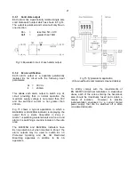
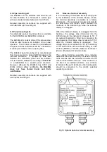
Configures the solid state alarm output to be open
‘no’ or to be closed
nC
in the non-alarm condition.
When deciding which is required, care should be
taken to ensure that the alarm output is fail safe as
illustrated in Fig 13.
no
Alarm output open in non-alarm condition
nC
Alarm output closed in non-alarm condition
CAUTION
When the 4/20mA supply is removed from
the loop powered indicator, both alarm
outputs will open irrespective of
conditioning. Therefore for fail safe
operation both alarm outputs should be
conditioned to be open in the alarm
condition
nC
.
To check or change the alarm output status, select
no
.
nC
from the alarm configuration menu and press
(
to reveal the setting. The function may be
changed by pressing the
&
or
*
button followed
by the
)
button to return to the alarm
configuration menu.
9.3.8
Hysteresis:
H5tr
Hysteresis is shown in the units that the indicator
has been calibrated to display.
To adjust the hysteresis select
H5tr
from the alarm
menu and press
(
which will reveal the existing
figure. The flashing digit can be adjusted using
the
&
and
*
push-buttons, and the
(
button
will move control to the next digit. When the
required hystersis has been entered press
)
to
return to the alarm configuration menu.
e.g. An indicator calibrated to display 0 to 10000,
with a high alarm set at 9000 and hysteresis of 200
will perform as follows:
The high alarm will be activated when increasing
indicator display equals 9000, but will not reset
until the indicator display falls below 8800.
9.3.9
Alarm delay:
dELA
This function delays activation of the alarm output
for an adjustable time following the alarm condition
occurring. The delay can be set in 1 second
increments between 0 and 3600 seconds. If a
delay is not required zero should be entered. To
adjust the delay select
dELA
from the alarm
configuration menu and press
(
which will reveal
the existing delay. The flashing digit of the delay
can be adjusted using the
&
and
*
push
buttons, and the
(
button to move control to the
other digits. When the required delay has been
entered press
)
to return to the alarm menu.
e.g. An indicator with a high alarm set at 9000 and
an alarm delay of 30 seconds will perform as
follows:
The alarm annunciator will start to flash when an
increasing indicator display equals 9000, but the
alarm output will not be activated until the alarm
condition has existed continuously for 30 seconds.
When the alarm output is activated, the alarm
annunciator will stop flashing and be permanently
activated.
If the
FL5H
function, which flashes the indicator
display when an alarm occurs, has been enabled,
it will not start to function until the alarm output is
activated.
See section 9.3.11