Control 1.3 Swimming Pool Control Unit
Technical Data
14
Technical Data
Terminal Assignment
Check which system components are available before starting the installation. Then observe the circuit
diagrams for connecting the unit that are included in this manual.
Pay attention to the information included in the circuit diagrams in this manual.
Always lay the lines / cables so that they are easily accessible or can be replaced in the case of
maintenance or other work.
Live cables must be selected according to the power load, distance and type of installation.
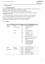
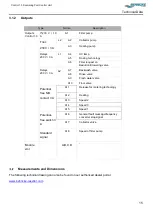
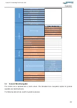
Please refer to the following table for the designation and type of the individual terminals.
Observe the function of the individual terminals (e.g. input or output signals).
A faulty connection may destroy the control unit or lead to a malfunction.
3.1.1
Inputs
Type
Name
Description
Inputs
Control 1.3
230 V
E1
Badutronic 93 feedback
Standard signal
E2
- Average fill level
- pH
- Redox
E3
PT1000
E4
Water temperature
E5
Collector temperature
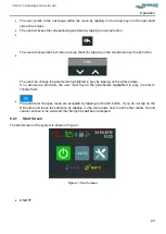
Digital
E6
Flow switch
E7
Float switch (skimmer)
E8
Roller shutter switch
E9
Fault signal on frequency converter
E10
Badutronic 93 filter cleaning is
running
E11
- Request on filter pump
(ext. overflow protection)
- Locking of filter pump
(ext. dry run protection)
- Average fill level
E12
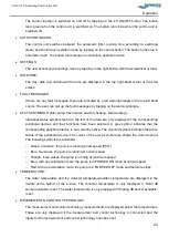
Inputs
Level control
Hang-in
electrodes
extE13
HE6: Overflow protection
extE14
HE5: Level compensation
extE15
HE4: Refilling off
extE16
HE3: Refilling on
extE17
HE2: Dry run protection
extE18
HE1: Reference electrode
Summary of Contents for Control 1.3
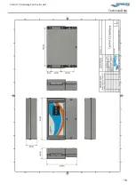
Page 18: ...Control 1 3 Swimming Pool Control Unit Technical Data 16 ...
Page 50: ...Control 1 3 Swimming Pool Control Unit Notes 48 Notes ...
Page 52: ......
Page 53: ......
Page 54: ......
Page 55: ......
Page 56: ......
Page 57: ......
Page 58: ......
Page 59: ......

