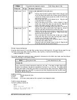
BE1-BPR Functional Description
4-33
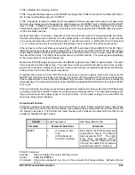
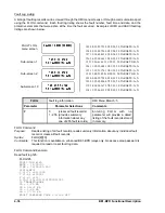
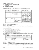
TLOG2= 92m 10:31:31.091 08/08/97
TLOG2= 0m* 05:51:09.254 08/07/97
TLOG2= 96m 03:33:11.669 08/07/97
TLOG2= 8m* 12:45:26.405 08/06/97
TLOG2= 47m 20:08:58.883 08/01/97
TLOG2= 8m* 17:10:07.259 08/01/97
TLOG2= 88m 16:44:12.855 08/01/97
TLOG2= 85m 17:01:23.307 07/25/97
TLOG2= 77m 18:29:55.697 07/17/97
TLOG2= 6m* 15:15:20.101 07/03/97
TLOG2= 55m 14:57:10.550 07/03/97
TLOG2= 94m 19:07:32.667 06/24/97
TLOG2= 70m 12:59:02.029 06/15/97
7,0(5 /2* 7/2*
7/2* P
7/2* P
7/2* P
Timer Log
The TIMER LOG provides timing diagnostics to aid in evaluating the relay settings or external timing. A log
for the last 40 events is stored in volatile memory. The log stores the time remaining on a timer/counter
when the logic programmed for the timer log alarm, using the PTLOG command, becomes TRUE (an event).
PTLOG alarm logic is programmable using simple BOOLEAN AND logic. Appropriate values must be
chosen for the logic variables in order for the time recorded to correspond to the timing diagnostic desired.
A Margin Log is a typical timing diagnostic. A delay timer is typically used to delay the breaker failure output
(BFO) until sufficient time has elapsed for the primary protection scheme to operate. The time left on the
timer when the BF logic is cleared is the margin value (refer to Section 1 for a detailed timing diagram
discussion and illustration). Knowing the time remaining on that timer provides feedback on the suitability
of the time delay and margin allowed for the protection scheme to operate. If there is a large discrepancy
between the calculated and actual margin, corrective action can be taken before a problem occurs.
Other timers may be set to measure some other parameter at the operator's discretion.
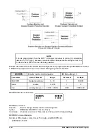
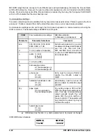
Use the PDIAG command to configure the timer log to set O14 or O15 (the software diagnostic alarm
outputs), if the timer value recorded is less than or greater than a programmed alarm value. A separate
alarm time can be set for each timer using the PTLOG command through the communications port. O14
or O15 can then be used to drive an output such as the ALARM output in order to provide an immediate
indication of a potential problem. The operator, upon receiving the alarm signal can query the relay through
the communication port or look at the DIAG screen in the RELAY STATUS MENU to identify the problem.
TLOG entries that exceed the alarm threshold are marked by an asterisk in the timer log (TLOG).
The timer log alarm will be reset when the diagnostic alarms are cleared by the "DIAG=0" command or reset
by using the RESET key when the TLOG alarm is displayed on the diagnostic alarm screen.
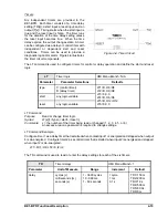
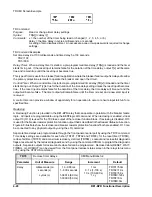
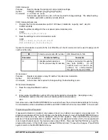
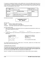
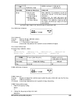
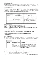
TIMER LOG data is saved in volatile memory and may be viewed on a terminal connected to a
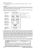
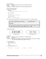
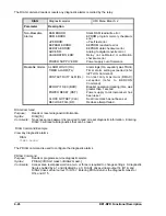
communications port or at the TIMER LOG menu screen of the HMI. TLOG events are displayed in reverse
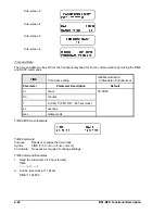
time order (last in - first out) sorted by timer number. Examples of TIMER LOG HMI screens are shown
below on the left. An example of a TIMER LOG ASCII report is shown below on the right.
TIMER LOG
menu screen
Sub-screen 1
Sub-screen 2
Sub-screen 40
Example.
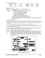
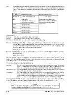
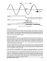
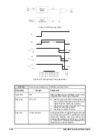
A margin log is created using the following settings. A logic diagram (using pre-programmed
logic BFL1) for the margin log is shown in Figure 4-9. The timing sequence and timer log is
illustrated in Figure 4-10.
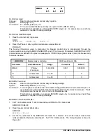
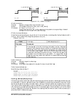
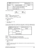
LT1=D,I2,/I2
Starts timer TD1 when input IN2 goes high.
PTLOG1=/O7,L,10
Time entry is logged when output 7 (O7) goes low. Margins of 10
milliseconds or less are marked with an asterisk (*) in the log.
TD1=100
Sets timer TD1 at 100 milliseconds.
TD1 starts timing when IN2 is energized. When O7 goes low, the difference in time between
the TD1 setting and O7 going low is recorded in the timer log.
Summary of Contents for BE1-BPR
Page 31: ...BE1 BPR Application 2 17...
Page 42: ...3 4 BE1 BPR Human Machine Interface Figure 3 4 BE1 BPR Relay Vertical Mount Front View...
Page 43: ...BE1 BPR Human Machine Interface 3 5 Figure 3 5 BE1 BPR Relay Vertical Mount Rear View...
Page 49: ...4 6 BE1 BPR Functional Description Figure 4 2 Enhanced BE1 BPR Menu Display Screens...
Page 50: ...BE1 BPR Functional Description 4 7 Figure 4 3 Standard BE1 BPR Menu Display Screens...
Page 94: ...5 4 BE1 BPR BESTlogic Figure 5 1 BESTlogic Function Blocks...
Page 121: ...BE1 BPR Installation 7 3 Figure 7 3 Overall Dimensions Vertical Mount...
Page 122: ...7 4 BE1 BPR Installation Figure 7 4 Overall Dimensions Side View Vertical Mount...
Page 123: ...BE1 BPR Installation 7 5 Figure 7 5 Panel Drilling Diagram Vertical Mount...

