2-2
BE1-BPR Application
4
6
8
10
12
14
16
18
20
22
1.05
1.25
2
5
20
40
MULTIPLES OF PICKUP
MAX. PICKUP TIME (ms)
PU=9.99A
PU=5.00A
PU=0.25A
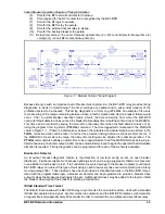
Figure 2-1. Maximum Pickup Timing
Instantaneous (50) Fault Detector Type 1
An instantaneous fault detector provides a typical one cycle pickup and one-quarter cycle dropout for high
speed operation. A three cycle software delay is imposed on any Type 1 fault detector when the current level
is less than 40 milliamperes above the pickup setting. This prevents noise induced trips from occurring. The
Type 1 is used in BF logic schemes and is programmed by setting the fault detector logic (LF) type to PI
(phase overcurrent) or NI (neutral overcurrent) and the digital filter selection to 1.
For the fault detector to pickup, the RMS value of the last cycle of current must be above the pickup setting.
Due to the analog input circuitry design, the RMS value is clamped (limited) at approximately 13 amperes.
As the multiple of pickup level increases, the pickup time decreases. Because of the limiting above 13
amperes, the pickup time does not appreciably decrease at high multiples of pickup. Also, the pickup may
be delayed up to one-quarter cycle because the RMS current is calculated every quarter cycle. However,
in no case will the pickup be slower than one and one-quarter cycles.
Figure 2-1 shows maximum pickup timing versus current input levels.
For the Type 1 fault detector to dropout, one of two conditions must occur. One, three sequential analog-to-
digital (A/D) samples must be less than one-fourth of the RMS current level for the last quarter-cycle
calculation. Two, the RMS current signal level must decrease to less than 75% of pickup. Samples are
made twelve times per line cycle and RMS current is calculated four times per line cycle. Three samples are
used to compensate for zero crossings and noise. A short dropout delay is advantageous for BF logic in
order to allow for the minimum timing margin in critical applications.
Figure 2-2 shows maximum dropout timing versus current input levels.
Summary of Contents for BE1-BPR
Page 31: ...BE1 BPR Application 2 17...
Page 42: ...3 4 BE1 BPR Human Machine Interface Figure 3 4 BE1 BPR Relay Vertical Mount Front View...
Page 43: ...BE1 BPR Human Machine Interface 3 5 Figure 3 5 BE1 BPR Relay Vertical Mount Rear View...
Page 49: ...4 6 BE1 BPR Functional Description Figure 4 2 Enhanced BE1 BPR Menu Display Screens...
Page 50: ...BE1 BPR Functional Description 4 7 Figure 4 3 Standard BE1 BPR Menu Display Screens...
Page 94: ...5 4 BE1 BPR BESTlogic Figure 5 1 BESTlogic Function Blocks...
Page 121: ...BE1 BPR Installation 7 3 Figure 7 3 Overall Dimensions Vertical Mount...
Page 122: ...7 4 BE1 BPR Installation Figure 7 4 Overall Dimensions Side View Vertical Mount...
Page 123: ...BE1 BPR Installation 7 5 Figure 7 5 Panel Drilling Diagram Vertical Mount...

