4-8
BE1-BPR Functional Description
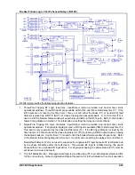
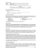
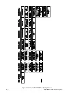
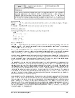
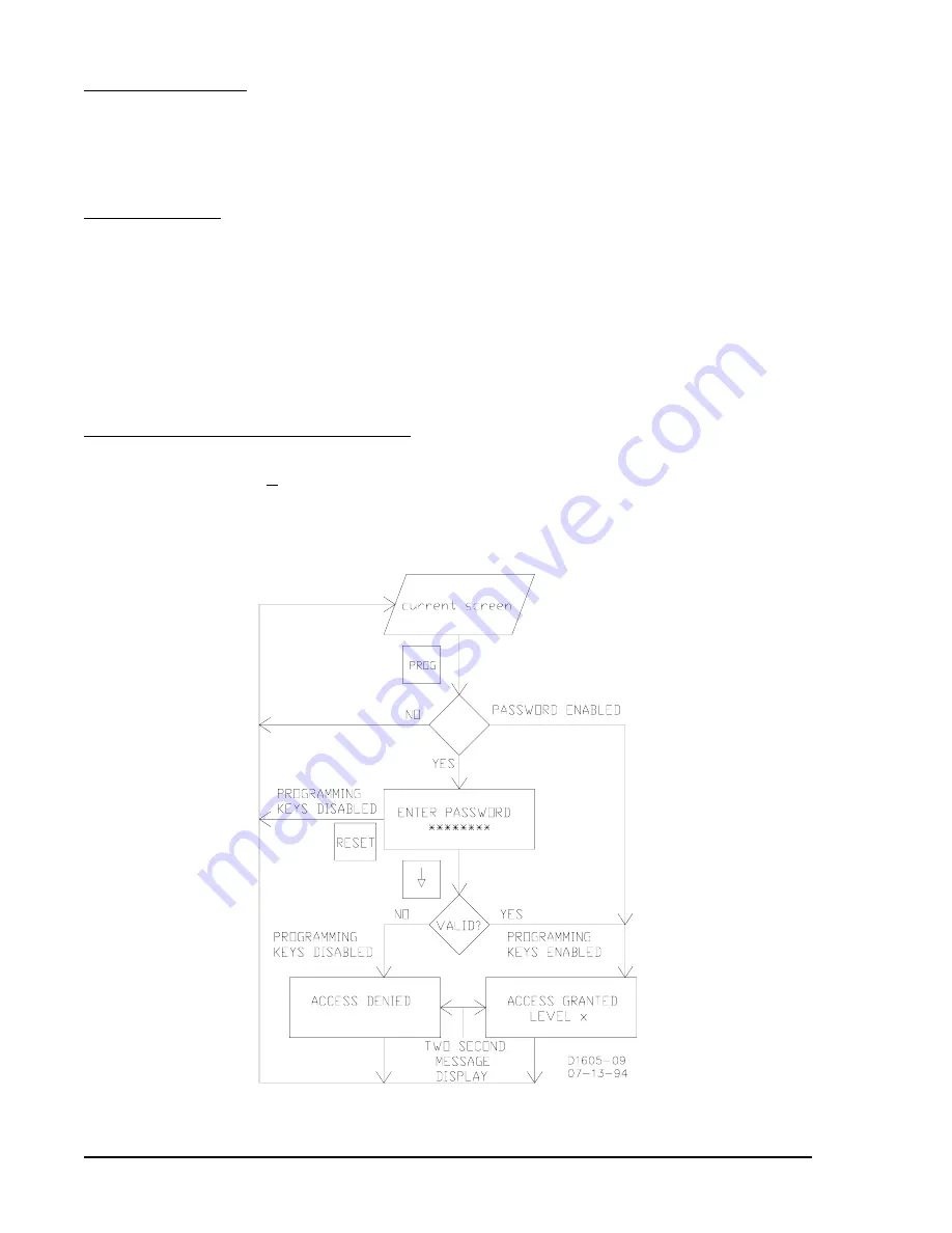
Figure 4-4. Accessing PROGRAM Mode from HMI
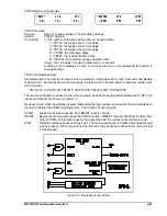
Selecting Menu Screen
To change a parameter (relay setting), select the menu screen by using the right arrow key until the appro-
priate menu screen is shown. With the RELAY SETUP screen displayed, press the down arrow key once
to display the pickup sub-screen. If PROGRAM mode has been enabled, the cursor will be under the first
digit for the PU1 setting. Figure 4-4 illustrates entering the PROGRAM mode.
Making the Change
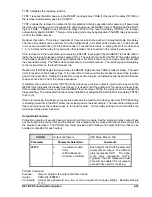
Press the right arrow key. The cursor moves to the second digit for PU1. Continue to press the right arrow
key until the cursor is under the units digit for PU2. To change the 4 to a 6, press the EDIT +/- key two times.
With the 6 displayed, press the right arrow key to position the cursor under the tenths digit. To change the
4 to a 3, two methods are available. The quickest method is to press the PROG key to make the EDIT +/-
key decrement. Now press the EDIT +/- key and the 4 changes to a 3. The next key that is pressed, other
than the EDIT +/- key, changes the EDIT +/- key back to the increment function. Another method is press
(increment) the EDIT +/- key nine times until the 3 is displayed. With 6.3 displayed for PU2, we now need
to exit the PROGRAM mode and save the changes. While in the PROGRAM mode, the BPR relay remains
on-line and the changes do not take effect until the PROGRAM mode is exited and the changes saved.
Saving Changes and Exiting PROGRAM Mode
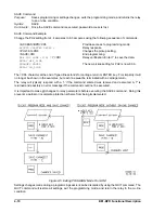
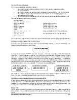
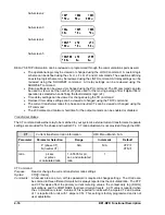
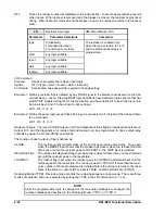
To save the settings and exit the PROGRAM mode, press and hold the PROG key for two seconds. The
SAVE CHANGES? (Y/N) - N screen appears and the cursor is under the N (see Figure 4-5). Press the EDIT
+/- key to select Y for yes. Press PROG key and the relay will go off-line for 1-2 seconds while the new
settings are saved and the BPR relay re-initializes itself.
Summary of Contents for BE1-BPR
Page 31: ...BE1 BPR Application 2 17...
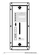
Page 42: ...3 4 BE1 BPR Human Machine Interface Figure 3 4 BE1 BPR Relay Vertical Mount Front View...
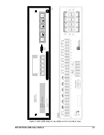
Page 43: ...BE1 BPR Human Machine Interface 3 5 Figure 3 5 BE1 BPR Relay Vertical Mount Rear View...
Page 49: ...4 6 BE1 BPR Functional Description Figure 4 2 Enhanced BE1 BPR Menu Display Screens...
Page 50: ...BE1 BPR Functional Description 4 7 Figure 4 3 Standard BE1 BPR Menu Display Screens...
Page 94: ...5 4 BE1 BPR BESTlogic Figure 5 1 BESTlogic Function Blocks...
Page 121: ...BE1 BPR Installation 7 3 Figure 7 3 Overall Dimensions Vertical Mount...
Page 122: ...7 4 BE1 BPR Installation Figure 7 4 Overall Dimensions Side View Vertical Mount...
Page 123: ...BE1 BPR Installation 7 5 Figure 7 5 Panel Drilling Diagram Vertical Mount...

