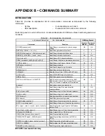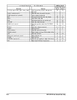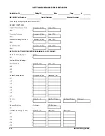
BE1-BPR Appendix
A-1
$33(1',;$
x
7(50,1$/(08/$7,21
This appendix provides instructions for configuring Windows 95
£
HyperTerminal and Windows
£
Terminal
to communicate with your BE1-BPR relay.
WINDOWS 95
£
HYPERTERMINAL
Step 1.
Click Start: Highlight Programs, Accessories, HyperTerminal.
Step 2.
Click HyperTerminal to open the folder.
Step 3.
Select the file or icon labeled
Hypertrm or Hypertrm.exe. Once the program has started, you
will be presented with a series of dialog boxes.
Step 4.
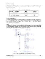
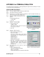
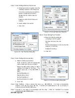
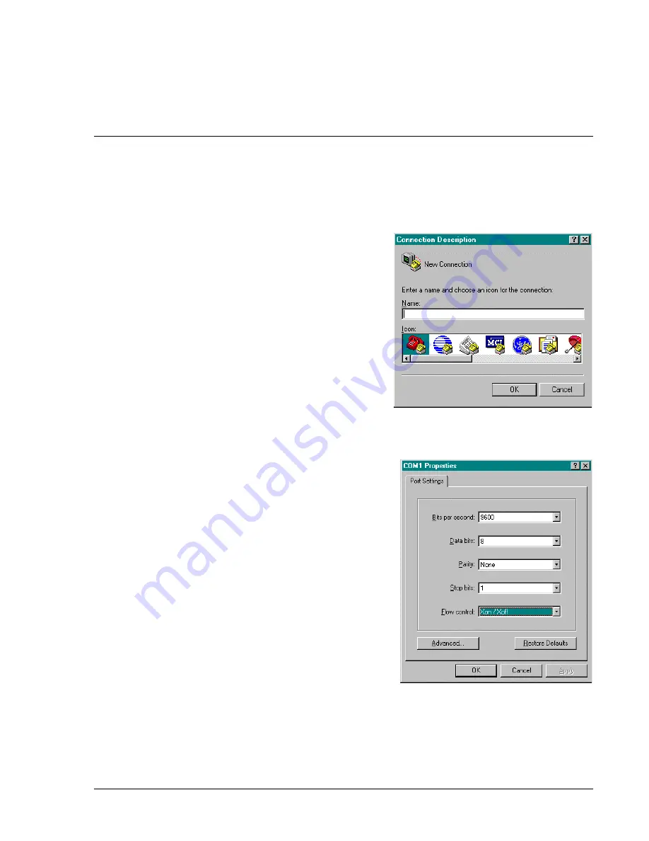
Dialog Box: CONNECTION DESCRIPTION See
Figure A-1.
a. Type the desired file name,
e.g., BE1-BPR
b. Click “OK”
Step 5.
Dialog Box: PHONE NUMBER
a. Click drop-down menu:
CONNECT USING
Select
Direct To ComX, where X is the port you
are using on your computer.
b. Click “OK”
Step 6.
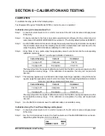
Dialog Box: COM
X Properties
a. Make the following selections using
Figure A-2 as a guide.
Set the bits per second setting so that it matches
the setting of the relay. The default baud rate of
the relay is 9600.
Set the data bits at
8.
Set the stop bits at
1.
Set flow control to
Xon/Xoff.
b. Click “OK”. This creates an icon with the file
name entered in Step 4 and places it in the
HyperTerminal folder. Future communication
sessions can then be started by clicking the
appropriate icon.
Step 7.
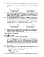
Click File/Properties on the menu bar. Click the
Settings tab.
a. Make the following selections:
Check the
Terminal Keys radio button.
Select
VT-100 emulation.
Set the Backscroll Buffer to the maximum setting of 500.
Figure A-1. Connection Description
Dialog Box
Figure A-2. COM Properties Dialog Box
Summary of Contents for BE1-BPR
Page 31: ...BE1 BPR Application 2 17...
Page 42: ...3 4 BE1 BPR Human Machine Interface Figure 3 4 BE1 BPR Relay Vertical Mount Front View...
Page 43: ...BE1 BPR Human Machine Interface 3 5 Figure 3 5 BE1 BPR Relay Vertical Mount Rear View...
Page 49: ...4 6 BE1 BPR Functional Description Figure 4 2 Enhanced BE1 BPR Menu Display Screens...
Page 50: ...BE1 BPR Functional Description 4 7 Figure 4 3 Standard BE1 BPR Menu Display Screens...
Page 94: ...5 4 BE1 BPR BESTlogic Figure 5 1 BESTlogic Function Blocks...
Page 121: ...BE1 BPR Installation 7 3 Figure 7 3 Overall Dimensions Vertical Mount...
Page 122: ...7 4 BE1 BPR Installation Figure 7 4 Overall Dimensions Side View Vertical Mount...
Page 123: ...BE1 BPR Installation 7 5 Figure 7 5 Panel Drilling Diagram Vertical Mount...


