BE1-BPR Application
2-5
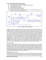
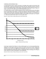
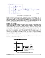
Figure 2-5. Multiple Breaker Arrangement
INITIATE
OUTPUT
RESET
TD[n]
D2635-11
04-01-98
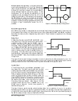
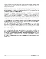
Figure 2-6. Delay Timer Operation
INITIATE
O U T P U T
TD[n]
R E S E T
D2635-12
04-02-98
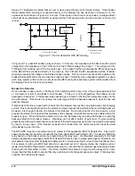
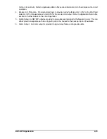
Figure 2-7. Control Timer Operation
Multiple Breaker Arrangements. In ring bus and breaker
and a half bus applications, CTs from two breakers are
often connected in parallel. If the BE1-BPR is connected
to these CTs as shown in Figure 2-5, low fault detector
pickup settings should be used with caution. In this
arrangement, the CT feeding the BE1-BPR can be
energized on the secondary side from the CT on the
adjacent circuit breaker. This results is current flowing in
the BE1-BPR even when the protected circuit breaker
has successfully interrupted the fault. This secondary
excitation current is generally negligible except when flux
remnants or high current/burden causes the CT to
saturate.
General Purpose Timers
Each BPR relay provides six independent timers for breaker failure timing and diagnostics. Each timer can
be programmed as a delay or a control timer and can have independent START and RESET conditions.
Each timer can also provide a diagnostic log and/or alarm. These features are explained in the following
paragraphs.
Delay Timer
A Delay timer has two inputs START and RESET, and
one output T[n]. The timer will not start until the start
condition becomes TRUE and the RESET input is
FALSE. Once the timer is started, a pre-programmed
time delay, TD[n], is loaded and the timer starts timing
out. Toggling of the START input has no effect once the
timer is started. The timer times out TD[n] time after the
timer is started unless the timer is RESET before the
time expires. If the timer times out, then the T[n] output
becomes TRUE. After timeout, T[n] remains TRUE until
the timer is RESET. Delay timer operation is illustrated
in Figure 2-6.
This type of timer is used to delay an operation in order to allow time for other processes to occur. For
example, in breaker failure applications, a delay timer is user to delay the breaker failure output until the
primary protection scheme has sufficient time to operate the breaker and open the circuit.
Control Timer
A Control timer has two inputs START and RESET, and
one output T[n]. The timer will not start until the start
condition becomes TRUE and the RESET input is FALSE.
Once the timer is started, a pre-programmed time delay,
TD[n], is loaded and the timer starts timing out. The timer
times out TD[n] time after the timer is started unless the
timer is RESET before the time expires. During the entire
period the timer is ON (i.e. not timed out and not reset),
the output T[n] is TRUE. If the timer times out, then the
T[n] output becomes FALSE. After timeout, the T[n]
remains FALSE until the timer is RESET and a new
START input is received. Control timer operation is
illustrated in Figure 2-7.
This type of timer is used to provide a limited window oftime for an operation to occur or to provide a
feedback signal to latch-in an input for a predetermined time. For example, in breaker failure applications,
a control timer can be used to latch-in a BFI input to ensure that once a BFI occurs a premature opening of
the BFI for whatever reason does not disable the BF logic.
Summary of Contents for BE1-BPR
Page 31: ...BE1 BPR Application 2 17...
Page 42: ...3 4 BE1 BPR Human Machine Interface Figure 3 4 BE1 BPR Relay Vertical Mount Front View...
Page 43: ...BE1 BPR Human Machine Interface 3 5 Figure 3 5 BE1 BPR Relay Vertical Mount Rear View...
Page 49: ...4 6 BE1 BPR Functional Description Figure 4 2 Enhanced BE1 BPR Menu Display Screens...
Page 50: ...BE1 BPR Functional Description 4 7 Figure 4 3 Standard BE1 BPR Menu Display Screens...
Page 94: ...5 4 BE1 BPR BESTlogic Figure 5 1 BESTlogic Function Blocks...
Page 121: ...BE1 BPR Installation 7 3 Figure 7 3 Overall Dimensions Vertical Mount...
Page 122: ...7 4 BE1 BPR Installation Figure 7 4 Overall Dimensions Side View Vertical Mount...
Page 123: ...BE1 BPR Installation 7 5 Figure 7 5 Panel Drilling Diagram Vertical Mount...

