background image

BE1-BPR Installation

7-5

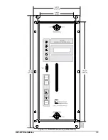
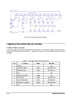
Figure 7-5. Panel Drilling Diagram (Vertical Mount)

Summary of Contents for BE1-BPR

Page 1: ...Publication 9 2720 00 990 Revision E 12 98 INSTRUCTION MANUAL for BE1 BPR BREAKER PROTECTION RELAY...

Page 2: ...PERFORM THE PROCEDURES PRESENTED IN THIS MANUAL INTRODUCTION This manual provides information concerning the operation and installation of the BE1 BPR Breaker Protection Relay To accomplish this the...

Page 3: ...Electric Co Highland IL 62249 December 1998 It is not the intention of this manual to cover all details and variations in equipment nor does this manual provide data for every possible contingency reg...

Page 4: ...r Type 3 2 4 Application of Fault Detectors 2 4 General Purpose Timers 2 5 Delay Timer 2 5 Control Timer 2 5 Timer Diagnostics 2 6 Reclosing Timers 2 6 Output Contacts 2 6 Trip Circuit Monitor Logic 2...

Page 5: ...n 4 5 Changing Parameters Using the Front Panel 4 5 Accessing PROGRAM Mode 4 5 Selecting Menu Screen 4 8 Making the Change 4 8 Saving Changes and Exiting PROGRAM Mode 4 8 Changing Parameters Using Com...

Page 6: ...TS 5 8 BE1 BPR PREPROGRAMMED PROTECTION SCHEMES 5 9 Breaker Failure Logic 1 For Standard Relays BFL1 5 10 Breaker Failure Logic 2 For Standard Relays BFL2 5 11 Breaker Failure Logic 3 For Standard Rel...

Page 7: ...7 11 Setup 7 11 IRIG B Connections 7 12 SECTION 8 CALIBRATION AND TESTING 8 1 CALIBRATION 8 1 Calibration Using A Communications Port 8 1 Calibration Using The Front Panel Display and Keyboard 8 1 OPE...

Page 8: ...e use of a current monitoring relay to determine whether or not current continues to flow into a faulted circuit after a breaker has been instructed to interrupt the circuit If current continues to fl...

Page 9: ...E1 BPR relays have two supervisory inputs WAIT and LOCKOUT WAIT stops the reclose sequence at any point and allows the sequence to continue when the WAIT input is removed LOCKOUT drives the reclose fu...

Page 10: ...the TLOG corrective action can be taken to correct the protection timing before a serious problem occurs If the MARGIN is too small or too large the delay timer setting can be adjusted for optimal ope...

Page 11: ...andard Common Format for Transient Data Exchange COMTRADE for Power Systems can also be used BESTView application software provides a simple terminal interface to communicate with the relay retrieve a...

Page 12: ...ple Current Detector Instantaneous Fault Detector 50 60 Hz RMS Filter Type 1 and 3 Dropout Time Dropout pickup ratio 90 typical One quarter cycle 4 2 milliseconds 60 hertz from the time the current fa...

Page 13: ...on the power supply model and the input voltage The input sensing range is the same as the dc power supply range Table 1 3 provides appropriate burden specifications Table 1 3 Input Contact Sensing Bu...

Page 14: ...0 Vac 125 250 Vdc Output contacts are rated as follows Make and carry 30 amperes for 0 2 second carry 7 amperes continuously and break 7 amperes Make and carry 30 amperes for 0 2 seconds carry 7 amper...

Page 15: ...applied between circuit groups and between circuit groupt and chassis ground in accordance with IEC 255 5 and ANSI IEEE C37 90 1989 Dielectric Tests Surge Withstand Capability Qualified to ANSI IEEE...

Page 16: ...ry These schemes take full advantage of the special features available in this relay without requiring the user to do any programming The user only selects the scheme desired and enters the pickup and...

Page 17: ...imately 13 amperes As the multiple of pickup level increases the pickup time decreases Because of the limiting above 13 amperes the pickup time does not appreciably decrease at high multiples of picku...

Page 18: ...ult detector should be used in applications where the current to be detected is less than 0 25 ampere Typically the response time for pickup and dropout depends on the number of cycles averaged and ho...

Page 19: ...protection will pickup for any fault that is sensed by the initiating relays Each fault detector can be independently set to monitor either the three phase current inputs or the neutral current input...

Page 20: ...of the START input has no effect once the timer is started The timer times out TD n time after the timer is started unless the timer is RESET before the time expires If the timer times out then the T...

Page 21: ...quence is interrupted and the relay will enter lockout Reset timer TD79R begins timing out when the RESET logic becomes TRUE breaker closes The reset timer is reset when the breaker trips If the reset...

Page 22: ...Logic Logic for monitoring the trip circuit and alarming for loss of voltage open fuse or loss of continuity open trip coil is provided in the preprogrammed breaker fail schemes Figure 2 8 shows input...

Page 23: ...the line will operate If the line is not cleared the relay logic will trip the backup breakers to clear the line and save the breaker If both ends of the line are open with no fault then the breaker m...

Page 24: ...um power rating the breaker resistor protection feature operates output 13 O13 which can be used as a block reclose output Breaker resistors are typically rated to handle X operations i e 5 operations...

Page 25: ...urrent level fault to be cleared This timer output would be ANDed with a different fault detector set to pickup on pre insertion resistor current levels The output of both AND gates would be ORed so t...

Page 26: ...ockout and reclose fail diagnostic flags are set reset by the programmable diagnostics Use the PDIAG command to program separate outputs for lockout and reclose fail The reclosing state RESET WAIT TIM...

Page 27: ...se two additional BFI inputs are available IN6 and IN7 to start delay timer T2 These inputs are not supervised by a fault detector If the BFI input is not reset by the time the timer times out BFO2 OU...

Page 28: ...Tripping BF Logic Features Output latch in provided and Control timer limits operational window If single pole tripping is used two additional BFI inputs are available IN6 and IN7 to start delay time...

Page 29: ...etector IN1 for breaker status and OUT4 for the arc detector output Refer to Application Data in this section for further details on the circuit operation 5 Retrip Output A RETRIP output is provided t...

Page 30: ...nput Output latch in provided and Control timer limits operational window If single pole tripping is used two additional BFI inputs are available IN6 and IN7 to start delay timer T2 These inputs are o...

Page 31: ...BE1 BPR Application 2 17...

Page 32: ...vided using fault detector 3 F3 for the MAF fault detector IN1 for breaker status and OUT4 for the arc detector output Refer to Application Data in this section for further details on the circuit oper...

Page 33: ...imer T2 This input is not supervised by a fault detector If the BFI input is not reset by the time the timer times out BFO2 OUT2 closes tripping the backup breakers Refer to the breaker failure timing...

Page 34: ...oil or be hooked to the backup trip coil if available 7 External Fault Trigger The enhanced BE1 BPR relay provides the ability to save the COMTRADE fault records for twelve events in memory at one tim...

Page 35: ...d a BFI input is available IN6 to start delay timer T2 This input is only supervised by the phase fault detector F1 If the BFI input IN6 is not reset by the time the timer T2 times out and the phase f...

Page 36: ...to Application Data in this section for further details on the circuit operation 6 Retrip Output A Retrip output is provided to give a backup trip signal to the breaker trip coil This can either prov...

Page 37: ...gle pole tripping is used a BFI input is available IN6 to start delay timer T2 This input is only supervised by the phase fault detector F1 If the BFI input IN6 is not reset by the time the timer T2 t...

Page 38: ...3 Refer to Application Data in this section for further details on the circuit operation 6 Retrip Output A retrip output is provided to give a backup trip signal to the breaker trip coil This can eith...

Page 39: ...EEN LED that turns ON to indicate power supply is operational CLOCK RED LED that turns ON to indicate that the real time clock RTC has not been set 50PU RED LED that turns ON to indicate that one or m...

Page 40: ...is entered If PROG key and then EDIT key are pressed the direction of the change is reversed until a new key other than EDIT is pressed When held for 2 seconds in PROGRAM mode brings up the SAVE scree...

Page 41: ...BE1 BPR Human Machine Interface 3 3 Figure 3 3 BE1 BPR Relay Horizontal Mount Front And Rear Views...

Page 42: ...3 4 BE1 BPR Human Machine Interface Figure 3 4 BE1 BPR Relay Vertical Mount Front View...

Page 43: ...BE1 BPR Human Machine Interface 3 5 Figure 3 5 BE1 BPR Relay Vertical Mount Rear View...

Page 44: ...inputs to the BPR relay They are Operating Power Contact Sensing Current Sensing Keyboard Serial Ports RS 232 RS 485 Operating Power Operating power for the internal circuitry is applied to the isola...

Page 45: ...ent circuitry monitors the power supply and the microprocessor to ensure that any problem in these areas automatically takes the BPR Relay off line and activates the alarm output Relay circuit functio...

Page 46: ...p setting If the filtered value is greater than the pickup setting then a fault detector logic flag F1 F2 or F3 is set for use by the output logic section If the fault detector logic is programmed as...

Page 47: ...tatus and diagnostic information and allows local programming capability LED backlighting is used to provide illumination for the LCD display Serial Ports RS 232 RS 485 Serial communication ports at t...

Page 48: ...ew any sub screen in any menu screen Default Screen Default screens are automatically displayed if no keys have been pressed for five minutes The standard default screen is the target screen The user...

Page 49: ...4 6 BE1 BPR Functional Description Figure 4 2 Enhanced BE1 BPR Menu Display Screens...

Page 50: ...BE1 BPR Functional Description 4 7 Figure 4 3 Standard BE1 BPR Menu Display Screens...

Page 51: ...hs digit To change the 4 to a 3 two methods are available The quickest method is to press the PROG key to make the EDIT key decrement Now press the EDIT key and the 4 changes to a 3 The next key that...

Page 52: ...ord is entered the relay responds with the access area provided by that password If an invalid password is entered an error message is returned ACCESS Command Purpose Reads or changes access area so t...

Page 53: ...F_LINE CHANGES SAVED The new pickup setting for PU2 is now 6 3 A RELAY ON_LINE The CR character at the end of typed lines stands for carriage return or ENTER key For simplicity it will no longer be sh...

Page 54: ...programmed it will not become effective until a SAVE command is given When a password is entered the relay looks for matching passwords Access is granted to all areas with passwords that match the ent...

Page 55: ...logic scheme is active NA NA 1 LR Set recloser function block logic NA NA 1 LT Set timer function block logic NA NA 1 PW Set password security 5 6 1 2 PTARGET Set targeting function NA NA 1 2 PU Set f...

Page 56: ...ress the key until the correct character is displayed Press the right arrow key to move to the next password character and press the key until the correct character is displayed Continue to enter pass...

Page 57: ...be viewed using the TARGET command TARGET Target information HMI Menu Branch 0 Comments This command reports target data for inputs 1 through 7 and outputs 1 through 5 Output target data must be progr...

Page 58: ...target operation and display Syntax PARGET iiiiiii ooooo Comments Access area one or two password is required to change settings PTARGET Command Example Program outputs 1 2 and 3 to target PTARGET 00...

Page 59: ...d or changed using the CT command The 200 millisecond minimum hold time for the output contacts can be enabled or disabled Transformer Ratios The CT command allows the relay to be matched to your syst...

Page 60: ...udes a parameter for entering the number of cycles to be averaged before pickup or dropout occurs Refer to Section 2 Application for a detailed description of the Type 2 fault detector Type 3 Fault De...

Page 61: ...type 2 amperes 0 05 1 00 0 01 level 1 A CT LFx type 1 or 3 amperes 0 05 2 00 0 01 PU1 2 00 PU2 2 00 PU3 0 20 10 level 1 A CT LFx type 2 amperes 0 01 0 10 0 01 cycles cycles 1 100 1 N A NOTE Types 1 a...

Page 62: ...meter Parameter Selections Defaults type C control timer D delay timer LT1 D O8 O8 LT2 D O9 O9 LT3 0 0 0 LT4 D O6 O6 LT5 D O12 O12 LT6 0 0 0 start any logic variable reset any logic variable LT Comman...

Page 63: ...f opportunity for an operation to occur or ensure input latch in for a specified time Reclosing A Reclosing Function is provided in the BE1 BPR relay that can operate in parallel with the breaker fail...

Page 64: ...disable reclose shot 3 Set the reset time at 30 seconds the fail time at 2 minutes and the maximum reclose time at 2 5 minutes TD791 3C TD792 2 5S TD793 0 TD79R 30S TD79F 120S TD79M 150S There are fo...

Page 65: ...ned I1 to be a 52a input I6 to be a wait input and I7 to be a drive to lockout input LR 1 O5 I1 I6 I7 Example 2 Define the same logic except that a 52b input is connected to I1 instead of the 52a and...

Page 66: ...the breaker is closed the recloser goes to the reset state Setting the reset time delay at zero will give an instantaneous reset and eliminate reclose shots 2 and 3 from the reclose sequence If enabl...

Page 67: ...nput contacts and output contacts Zeroes are shown for input contacts that are open and outputs that are de energized Ones are shown for input contacts that are closed and outputs that are energized S...

Page 68: ...of the phase A B C and Neutral inputs I Measured current values HMI Menu Branch 2 Comments This command returns the primary value of all current inputs The primary current value is calculated using t...

Page 69: ...d BKROP 1 SEC BKR Breaker operation clearing time was greater than 1 second POWER RESET RST Power supply to microprocessor has been reset CLOCK NOT SET CLK Real time clock has not been set RECLOSE FAI...

Page 70: ...G 0 command RF Flag is set when the Reclose Fail Alarm occurs Flag is reset when the breaker closes LO Flag is set when the recloser goes to lockout Flag is reset when the recloser comes out of lockou...

Page 71: ...r OPEN CLOSED based on the logic defined by the BKROPS command Breaker position is also reported by the STATUS command BKROPS Breaker operations status HMI Menu Branch 3 Parameter Unit of Measure Rang...

Page 72: ...operate time is the average time from when the breaker contacts start to part to when the arc across the contacts is extinguished Tbo w T Tc The duty on each pole is accumulated and calculated as fol...

Page 73: ...ing HMI Menu Branch N A Parameter Unit of Measure Range Increment Default DMAX Primary A2 seconds 0 6 8E38 0 001 0 000E00 Tc milliseconds 0 50 1 0 Ti milliseconds 0 50 1 0 BKRCON Command Purpose Read...

Page 74: ...stor value Ires VLN R This value Ires will be less than the maxi mum short circuit rating ISC for the breaker Typically a breaker opening resistor will be rated to allow a maximum number of operations...

Page 75: ...If MAXOPS is programmed to zero the resistor heating diagnostic is disabled BKRRES Breaker resistor monitoring data HMI Menu Branch 3 Parameter Unit of Measure Range Increment Default MAXOPS breaker o...

Page 76: ...the PDIAG command to configure the timer log to set O14 or O15 the software diagnostic alarm outputs if the timer value recorded is less than or greater than a programmed alarm value A separate alarm...

Page 77: ...s can be used to specify when timer log is triggered alm_type H L or 0 H Alarm occurs when the remaining time at the point the timer logic becomes true is higher than the alarm_time setting L Alarm oc...

Page 78: ...If more than 40 logs are generated then the oldest log is overwritten If a logged time has triggered a timer log alarm then that timer is marked with an asterisk in the timer log TLOG Command Purpose...

Page 79: ...hat were active at the time the fault occurred Examples of HMI and ASCII fault log listings are shown below FAULT LOG menu screen Sub screen 1 Sub screen 2 Sub screen 10 FLOG Fault log information HMI...

Page 80: ...r is reset and re armed after the TRIGGER definition becomes FALSE The fault data recorded is as follows Fault log number 1 255 Date and time of the start of fault data to one millisecond resolution T...

Page 81: ...Purpose Obtains a COMTRADE fault report Syntax FLT type Comments This function is available on enhanced BE1 BPR relays only No access area password is required to retrieve a COMTRADE fault report FLT...

Page 82: ...he zeros in the file name as long as the same file naming convention is used for the CFG and DATA files 6 Once the file has been named select start if necessary to begin transfer 7 Once the configurat...

Page 83: ...ands TIME Time clock setting HMI Menu Branch 5 Standard 6 Enhanced Parameter Parameter Description Default hr hours 00 00 00 mn minutes f A AM P PM OR 24 hour clock sc seconds msc milliseconds TIME HM...

Page 84: ...date format to be changed The date can be displayed with the day followed by the month or vice versa The time can displayed in a 12 hour format or a 24 hour format PCLK Clock display mode HMI Menu Br...

Page 85: ...ranch 5 Standard 6 Enhanced U Parameter Parameter Selections Comments rate 300 600 900 1200 2400 4800 9600 or 19K Not all combinations of d p and s areallowed Allowed combinations are 7O1 7E1 7N2 8O1...

Page 86: ...COM0 ID Command Purpose Reads or programs a relay ID number for polled communication Syntax ID id 0 254 Comments Access area one required to change setting Default setting is zero ID Command Examples...

Page 87: ...sword has already been entered using the ACCESS password command PW PW1 ABC B PW2 123 FPW3 XYZ F PW4 BPR F 2 Change Password 2 from front access and no password to front and rear access with a passwor...

Page 88: ...Screen Example CAL Command Purpose Read or change calibration values Syntax CAL x amps Comments x 1 low range 2 high range Access area one password is required to make calibration changes CAL Command...

Page 89: ...reen 0 of the menu branch PDISPLAY Command Purpose Read or program the default HMI display screen Syntax PDISPLAY default_menu default_screen Comments Access area password one two or three required to...

Page 90: ...ered The VER command will return the software version number as well as the relay model part and serial number VER Relay version information HMI Menu Branch 5 Standard 6 Enhanced Comments This command...

Page 91: ...sample interval is 1 667 milliseconds After each sample the status of all inputs timers and other functions are updated and then the output status is updated by evaluating logic equations associated...

Page 92: ...active logic LOGIC BFL3E 2 Change the active logic to BFL1E LOGIC BFL1E LOGIC VARIABLES Logic variables entered in equation form control the actual relay outputs Names assigned to the inputs timers a...

Page 93: ...ual Output 3 OUT3 TB1 9 10 O4 Virtual Output 4 OUT4 TB1 11 12 O5 Virtual Output 5 OUT5 TB1 13 14 O6 Virtual Output 6 N A N A O7 Virtual Output 7 N A N A O8 Virtual Output 8 N A N A O9 Virtual Output 9...

Page 94: ...5 4 BE1 BPR BESTlogic Figure 5 1 BESTlogic Function Blocks...

Page 95: ...e name does not affect the other logic definitions If changes are attempted prior to changing the logic name the relay will respond with an error message CUSTOM LOGIC NAME NOT SELECTED LN Custom logic...

Page 96: ...he logic equation for O13 is displayed as ROP_LIMIT if the Recloser function is not used and BKRRES is defined Outputs O14 and O15 are programmable diagnostic outputs that allow one or more diagnostic...

Page 97: ...Therefore when output 1 turns TRUE it will remain TRUE latching itself on independently of I1 until timer T3 turns off Boolean equation LO1 T3 I1 O1 Internal format LO1 T3I1 T3O1 Example 4 Overcoming...

Page 98: ...chemes can be used in a large number of applications with no special programming required The unneeded inputs or outputs may be left open to disable the function Unused CT inputs should be shorted to...

Page 99: ...d that a NO output be used to drive an external low cost auxiliary relay The NC output of the auxiliary relay can then be used and the electronics can still be drawn out Alternately an external switch...

Page 100: ...12 LI5 4 12 LI6 4 12 U LI7 4 12 LR 0 0 0 0 0 LT1 D O8 O8 LT2 D O9 O9 LT3 0 0 0 LT4 D O6 O6 LT5 D O12 O12 LT6 0 0 0 LOA T4 O15 LO1 T1O7 LO2 T2 LO3 T1O7 LO4 T5 LO5 O8 O9 LO6 I1 I2 LO7 F1 F2 LO8 I3 I4 I...

Page 101: ...LI6 4 12 U LI7 4 12 LR 0 0 0 0 0 LT1 D O8 O8 LT2 D O9 O9 L T3 C O10 O10 LT4 D O6 O6 LT5 D O12 O12 LT6 0 0 0 LOA T4 O15 LO1 O3 LO2 O3 LO3 T1O7 F1T2 O1O7 LO4 T5 LO5 T3 LO6 I1 I2 LO7 F1 F2 LO8 T3O11 LO9...

Page 102: ...4 12 U LI7 4 12 LR 0 0 0 0 0 LT1 D O8 O8 LT2 D O9 O9 LT3 O10 O10 LT4 D O6 O6 LT5 D O12 O12 LT6 0 0 0 LOA T4 O15 LO1 O3 LO2 O3 LO3 T1O7 F1T2 O1O7 LO4 T5 LO5 T3 LO6 I1 I2 LO7 F1 F2 LO8 T3O11 LO9 T3I6 T3...

Page 103: ...I4 1 12 LI5 1 12 LI6 1 12 U LI7 1 12 LR 0 0 0 0 0 LT1 D O8 O8 LT2 D I6 I6 LT3 0 0 0 LT4 D O6 O6 LT5 D O12 O12 LT6 0 0 0 LOA T4 O14 O15 LO1 T1O7 LO2 T2 LO3 O13 LO4 T5 LO5 O8 I6 LO6 I1 I2 LO7 F1 F2 LO8...

Page 104: ...2 LI6 4 12 U LI7 4 12 LR 0 0 0 0 0 LT1 D O8 O8 LT2 D O9 O9 LT3 C O10 O10 LT4 D O6 O6 LT5 D O12 O12 LT6 0 0 0 LOA T4 O14 O15 LO1 O2 LO2 T1O7 F1T2 O1O7 LO3 O13 LO4 T5 LO5 T3 LO6 I1 I2 LO7 F1 F2 LO8 T3O1...

Page 105: ...6 4 12 U LI7 4 12 LR 0 0 0 0 0 LT1 D O8 O8 LT2 D O9 O9 LT3 O10 O10 LT4 D O6 O6 LT5 D O12 O12 LT6 0 0 0 LOA T4 O14 O15 LO1 O2 LO2 T1O7 F1T2 O1O7 LO3 O13 LO4 T5 LO5 T3 LO6 I1 I2 LO7 F1 F2 LO8 T3O11 LO9...

Page 106: ...ions not changed will be left as they were 4 Review the changes using LINF0 new_name or the LF LI LT and LO commands 5 If the new logic is to become the active logic then type LOGIC new_name 6 Save th...

Page 107: ...re information refer to Section 2 Breaker Failure Protection With Pre Insertion Resistors LN BFRES LF1 PI 1 LF2 NI 1 LF3 PI 2 LI1 4 12 LI2 4 12 LI3 4 12 LI4 4 12 LI5 4 12 LI6 4 12 LI7 4 12 LR 0 0 0 0...

Page 108: ...1 LF3 PI 2 LI1 4 12 LI2 4 12 LI3 4 12 LI4 4 12 LI5 4 12 LI6 4 12 LI7 4 12 LR 1 O10 I1 I6 O11 LT1 D O8 O8 LT2 D I5 I5 LT3 0 0 0 LT4 D O6 O6 LT5 D O12 O12 LT6 0 0 0 LOA T4 O15 LO1 T1O7 T2 LO2 T2 T2 LO3...

Page 109: ...ic 5 19 U U The non maskable alarms are always ORed with the programmable diagnostics to provide an alarm output Note Breaker resistor protection is included in the logic scheme only if the BKRRES com...

Page 110: ...l communication port COM0 is intended for short term local communication Hardware security is provided by a wire seal on the front panel which limits unauthorized access Password protection provides a...

Page 111: ...nds to change parameters are identified by an equals sign being included in the command The new operating parameters to the right of the equals sign are intended to replace the current operating param...

Page 112: ...D O6 O6 LT5 D O12 O12 LT6 0 0 0 LOA T4 O15 LO1 O3 LO2 O3 LO3 T1O7 F1T2 O1O7 LO4 T5 LO5 T3 LO6 I1 I2 LO7 F1 F2 LO8 T3O11 LO9 T3I6 T3I7 LO10 I6 I7 O11 LO11 I3 I4 I5 LO12 F3I1 LOGIC USER FREQ 60 ID 0 PU...

Page 113: ...O12 O12 LT6 0 0 0 LOA T4 O15 LO1 O3 LO2 O3 LO3 T1O7 F1T2 O1O7 LO4 T5 LO5 T3 LO6 I1 I2 LO7 F1 F2 LO8 T3O11 LO9 T3I6 T3I7 LO10 I6 I7 O11 LO11 I3 I4 I5 LO12 F3I1 LOGIC USER FREQ 60 PRESS ANY KEY TO CONTI...

Page 114: ...Syntax BKRRES MAXOPS reset Ires Reference Section 4 Functional Description Software Functional Description Breaker Status Breaker Resistor Diagnostics CAL Command Purpose Read or change calibration va...

Page 115: ...ription Relay Status ID Command Purpose Reads or programs a relay ID number for polled communication Syntax ID id 0 255 Reference Section 4 Functional Description Software Functional Description Maint...

Page 116: ...e Output Contact Testing PCLK Command Purpose Reads or changes the time clock time date format Syntax PCLK date_format M D time_format 12 24 Reference Section 4 Functional Description Software Functio...

Page 117: ...nce Section 4 Functional Description Software Functional Description Changing Parameters Using Communication Ports RESET Command Purpose Clears latched target data Syntax RESET Reference Section 4 Fun...

Page 118: ...Functional Description Relay Status TIME Command Purpose Reads or changes the time clock Syntax TIME hr mn f sc msc Reference Section 4 Functional Description Software Functional Description Maintena...

Page 119: ...e BE1 BPR case is hard wired to earth ground using the ground terminal on the rear of the unit 4 When the unit is in service the controls should be protected by the plastic cover supplied This limits...

Page 120: ...7 2 BE1 BPR Installation Figure 7 1 Overall Dimensions Figure 7 2 Cutout Dimensions Panel Mount...

Page 121: ...BE1 BPR Installation 7 3 Figure 7 3 Overall Dimensions Vertical Mount...

Page 122: ...7 4 BE1 BPR Installation Figure 7 4 Overall Dimensions Side View Vertical Mount...

Page 123: ...BE1 BPR Installation 7 5 Figure 7 5 Panel Drilling Diagram Vertical Mount...

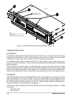
Page 124: ...l position the escutcheon plate in the alternate location and install the four screws 3 that are provided with the optional escutcheon plate kit Refer to Figure 7 7 for the alternate location side vie...

Page 125: ...xternal Sensing Connections Westinghouse FT31 and FT32 cases CONNECTIONS Incorrect wiring may result in damage to the unit Typical external sensing connections are shown in Figure 7 8 Connections for...

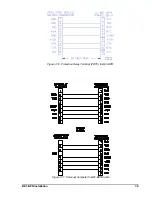
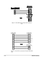
Page 126: ...ers functions names and signal directions are shown in Table 7 1 Figures 7 10 through 7 13 provide RS 232 cable connection diagrams Table 7 1 RS 232 Pinouts Port0 And Port1A Pin Function Name Directio...

Page 127: ...BE1 BPR Installation 7 9 Figure 7 10 Protective Relay Terminal PRTU to BE1 BPR Figure 7 11 Personal Computer to BE1 BPR Cable...

Page 128: ...7 10 BE1 BPR Installation Figure 7 12 RFL 9660 Protective Relay Switch to BE1 BPR Cable Figure 7 13 SEL 2020 Communications Processor to BE1 BPR Cable...

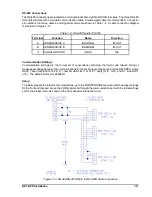
Page 129: ...IVE A SDA RDA IN OUT B SEND RECEIVE B SDB RDB IN OUT G SIGNAL GROUND GND N A Communication Settings Communication settings are the formal set of conventions controlling the format and relative timing...

Page 130: ...IRIG B Connections The IRIG B connections are located on a terminal block shared with the RS 485 terminals Terminal designations and functions are shown in Table 7 3 Table 7 3 IRIG B Pinouts Terminal...

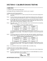
Page 131: ...t Sensing Current Command 1 ampere CT 2 amperes CAL1 2 5 ampere CT 10 amperes CAL1 10 The relay will perform the required calibration and verify that the ADC counts per ampere are within the acceptabl...

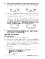
Page 132: ...tion begins The relay will perform the required calibration and verify that the ADC counts per ampere are within the acceptable accuracy range While the calibration is in progress the display will sho...

Page 133: ...heme without copying any previous file ACCESS password or ACCESS BPR if password not used LN name of new scheme allows scheme to be changed Use LO LF LC LT commands as required to change logic Disable...

Page 134: ...onitoring a breaker with an opening resistor then enter the breaker resistor information by using the BKRRES commands Step 17 If the relay has the breaker contact duty log option then enter the breake...

Page 135: ...using surface mount technology and are not designed to be field serviceable Should the relay require service the draw out assembly should be returned to the factory for repair Contact the Power Syste...

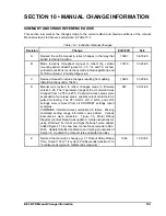
Page 136: ...ual was revised to reflect changes made in firmware version 3 26 The r parameter range of the LI command was changed from 1 255 to 4 255 Password access areas were expanded to four areas area 4 enable...

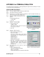
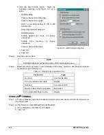
Page 137: ...To ComX where X is the port you are using on your computer b Click OK Step 6 Dialog Box COMX Properties a Make the following selections using Figure A 2 as a guide Set the bits per second setting so t...

Page 138: ...o not become active until the settings are saved Step 9 HyperTerminal is now ready to communicate with the relay Table A 1 describes the required connection for each RS 232 port Table A 1 RS 232 Commu...

Page 139: ...ollowing selections Under Connector select the appropriate communiation port for your computer Adjust the Baud Rate setting so that it matches the setting of the relay The default baud rate of the BE1...

Page 140: ...OG and FAULT data NA 5 FLT type L Read COMTRADE report for fault xxx NA NA FREQ freq Read Change power system frequency 5 6 HELP H or HELP H cmd or HELP1 H1 HELP H returns information about using HELP...

Page 141: ...Reset latched target data 0 0 SAVE Exit programming mode and save changes NA NA SHOWSET Read relay setup parameters NA NA SNAME name L Read Change station name for the COMTRADE report NA NA STATUS Rea...

Page 142: ...relative to your protection system These settings sheets may be removed and photocopied This listing is grouped in the following order with a reminder at the end to exit with the save settings procedu...

Page 143: ...ns Password 8 Char Ports F R B PW3 Control Functions Password 8 Char Ports F R B PW4 BESTLOGIC SETTINGS FOR USER PROGRAMMABLE LOGIC SCHEME Name for User Prog Logic Name LN Function Blk Logic Settings...

Page 144: ...ACTIVE PROTECTION AND CONTROL LOGIC Active Logic Scheme Name LOGIC POWER SYSTEM SETTINGS Nominal Frequency Hz 50 60 FREQ REAR COM PORT ADDRESS SETTINGS Rear RS232 RS485 Port Address ID 0 disabled 1 25...

Page 145: ...k Display Mode Date M or D Time 12 or 24 PCLK LCD Default Display Menu Branch Screen PDISPLAY Communications Front RS232 Port Baud DPS Reply Ack A0 1 Echo Mode E0 1 HW Handshake H0 1 COM0 Front RS232...

Page 146: ...e breaker access PW1 PW3 BREAKER MONITORING SETTINGS Breaker Contact Duty Settings DMAX x xxxE xx A2 t Delta t Contact msec Delta t Current msec BKRCON Breaker Status Op Counter Breaker Open Logic BKR...

Page 147: ...7 DLOG command 4 30 6 6 F Fault Detector 1 5 2 1 4 17 Dropout Time 1 5 Instantaneous 2 2 LF Command 4 17 Moving average filter 2 3 PU Command 4 18 Pickup Accuracy 1 5 Pickup Range 1 5 Pickup Time 1 5...

Page 148: ...2 4 20 LR Command 4 22 TD79 Command 4 21 Relay Status 4 24 DIAG Command 4 26 I Command 4 25 PDIAG Command 4 27 STATUS Command 4 25 TEST Command 4 27 RESET Command 4 15 RS 485 Connections 7 11 S SAVE...

Reviews: