


1-2
General Information
BE1-67
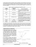
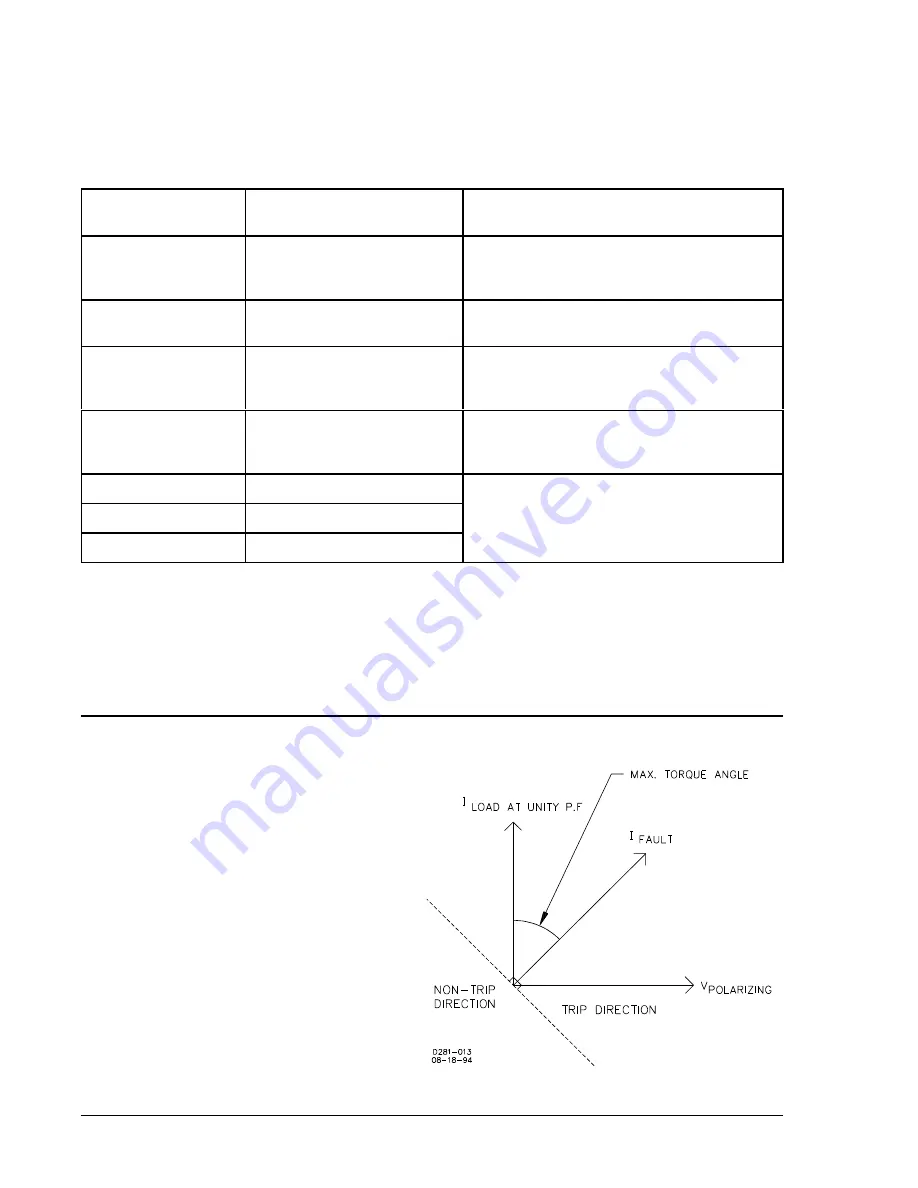
Figure 1-2. Trip Direction Defined
Twelve standard time-current characteristic curves are available to aid in the coordination of this relay with
other protective devices in the system. These include seven characteristic curves that are standard in North
America and five that are compatible with British or IEC standards requirements. In addition, an option allows
the relay to be supplied with all of these curves any of which may be switch selected to suit requirements at
the time of installation.
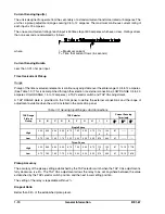
Table 1-1. Selection Considerations For Characteristic Curves
Style
Designation
Characteristic
Shape
Special Characteristics
B1
Short Inverse
Relatively short time, desirable where
preserving system stability is a critical
factor.
B2, E2
Long Inverse
Provides protection for starting motors and
overloads of short duration.
B3
Definite Time
Definite Time Fixed time delay according to
the time dial setting. Useful for sequential
tripping schemes.
B4, E4
Moderately Inverse
Accommodates moderate load changes as
may occur on parallel lines where one line
may occasionally have to carry both loads.
B5, E5
Inverse
Provide additional variations of the inverse
characteristic, thereby allowing flexibility in
meeting load variations, or in coordinating
with other relays.
B6. E6
Very Inverse
B7, E7
Extremely Inverse
If the supply to the protected portion of the system is constant, and if the magnitude of the fault current is
determined primarily by the location of the fault on the line, the selection of a more inverse time characteristic
is more desirable to provide selective coordination with adjacent line protection. However, if the capacity of
the supply varies significantly over a period (such as a day), a less inverse time or even the definite time
characteristic, may be preferred to provide smoother coordination.
LIMITED REGION OF OPERATION
A limited region-of-operation option is available to
provide additional protection against false tripping
on mutually coupled lines. Faults on adjacent lines
that share the same poles, towers or right-of-way
may induce currents on the protected line which
appear as fault currents in the tripping direction.
The limited region of operation mode provides
discrimination between faults on the protected line
and faults on the adjacent line. To order this option,
specify option 3-5 or 3-6.
One consideration in applying a phase directional
overcurrent relay is the definition of trip direction.
For most applications, the setting of the relay
directional element is based upon the impedance
characteristics of a given circuit. This angle is then
used as the maximum torque angle and any current
flowing in the half-plane defined by this angle is
considered to be in the trip direction.
Summary of Contents for BE1-67
Page 23: ...BE1 67 General Information 1 17 Figure 1 13 Timing Type B2 Long Inverse Drawing Number 99 0931...
Page 26: ...1 20 General Information BE1 67 Figure 1 16 Timing Type B5 Inverse Drawing Number 99 0929...
Page 27: ...BE1 67 General Information 1 21 Figure 1 17 Timing Type B6 Very Inverse Drawing Number 99 0928...
Page 39: ...2 6 Human Machine Interface BE1 67 Figure 2 3 Location of Assemblies Controls and Indicators...
Page 47: ...4 2 Installation BE1 67 Figure 4 1 Outline Dimensions Front View...
Page 48: ...BE1 67 Installation 4 3 Figure 4 2 Outline Dimensions Rear View...
Page 49: ...4 4 Installation BE1 67 Figure 4 3 Outline Dimensions Side View Semi Flush Mounting...
Page 50: ...BE1 67 Installation 4 5 Figure 4 4 Outline Dimensions Side View Projection Mounting...
Page 51: ...4 6 Installation BE1 67 Figure 4 5 Panel Drilling Diagram Semi Flush Mounting...
Page 52: ...BE1 67 Installation 4 7 Figure 4 6 Panel Drilling Diagram Projection Mounting...
Page 54: ...BE1 67 Installation 4 9 Figure 4 8 Single Phase AC Connections...
Page 55: ...4 10 Installation BE1 67 Figure 4 9 Three Phase AC Connections...
Page 56: ...BE1 67 Installation 4 11 Figure 4 10 BE1 67 Single Phase Internal Connection Diagram...
Page 57: ...4 12 Installation BE1 67 Figure 4 11 BE1 67 Three Phase Internal Connection Diagram...
Page 62: ...BE1 67 Testing 5 5 Figure 5 3 Blank Polar Graph Form Figure 5 4 Blank Polar Graph Form...