


5-8
Testing
BE1-67
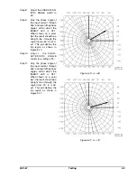
Figure 5-8.
"
= 30°
Figure 5-9.
"
= 45°
Procedure 2
(For use with switch selectable CHARACTERISTIC ANGLE, options 3-2 and 3-4.)
Step 1.
Perform the preliminary
setup.
Step 2.
Turn the CHARACTER-
ISTIC ANGLE switch to
30°.
Step 3.
Adjust the input voltage
source for 120 Vac at a
phase angle of 0°.
Step
4.
Adjust the input
current
source for 1.0 ampere
(LOW range ) or 3.0
amperes (HIGH range) at a
phase angle of +90° (90°
leading). The INHIBIT LED
indicator should be OFF,
and the TIMING LED ON
(i.e., the appropriate phase
LEDs thereof on a 3-phase
unit). If not, current or
voltage connections are
reversed and should be
corrected.
Step 5.
Vary the phase angle of the
input current through 360°
and record the phase
angles at which the
INHIBIT LED is OFF. When
shown on a polar plot, the
result should be a straight
line (through the origin )
from -30° to +150° ±5°.
This plot defines the trip
region as shown in Figure
5-8.
Step 6.
Adjust the CHARACTER-
ISTIC ANGLE control to a
setting of 45°.
Step 7.
Vary the phase angle of the
input current through 360°
and record the phase
angles within which the
INHIBIT LED is OFF. When
shown on a polar plot, the
result should be a straight
line (through the origin)
from -45° to +135° ±5°.
This plot defines the trip region as shown in Figure 5-9.
Summary of Contents for BE1-67
Page 23: ...BE1 67 General Information 1 17 Figure 1 13 Timing Type B2 Long Inverse Drawing Number 99 0931...
Page 26: ...1 20 General Information BE1 67 Figure 1 16 Timing Type B5 Inverse Drawing Number 99 0929...
Page 27: ...BE1 67 General Information 1 21 Figure 1 17 Timing Type B6 Very Inverse Drawing Number 99 0928...
Page 39: ...2 6 Human Machine Interface BE1 67 Figure 2 3 Location of Assemblies Controls and Indicators...
Page 47: ...4 2 Installation BE1 67 Figure 4 1 Outline Dimensions Front View...
Page 48: ...BE1 67 Installation 4 3 Figure 4 2 Outline Dimensions Rear View...
Page 49: ...4 4 Installation BE1 67 Figure 4 3 Outline Dimensions Side View Semi Flush Mounting...
Page 50: ...BE1 67 Installation 4 5 Figure 4 4 Outline Dimensions Side View Projection Mounting...
Page 51: ...4 6 Installation BE1 67 Figure 4 5 Panel Drilling Diagram Semi Flush Mounting...
Page 52: ...BE1 67 Installation 4 7 Figure 4 6 Panel Drilling Diagram Projection Mounting...
Page 54: ...BE1 67 Installation 4 9 Figure 4 8 Single Phase AC Connections...
Page 55: ...4 10 Installation BE1 67 Figure 4 9 Three Phase AC Connections...
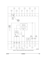
Page 56: ...BE1 67 Installation 4 11 Figure 4 10 BE1 67 Single Phase Internal Connection Diagram...
Page 57: ...4 12 Installation BE1 67 Figure 4 11 BE1 67 Three Phase Internal Connection Diagram...
Page 62: ...BE1 67 Testing 5 5 Figure 5 3 Blank Polar Graph Form Figure 5 4 Blank Polar Graph Form...