


1-8
General Information
BE1-67
Conclusions
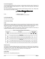
Taking into consideration the requirements imposed by each of three possible fault conditions, the five
required settings for the relay at breaker A in this application are summarized in Table 1-2.
Table 1-2. Required Breaker Settings
Variable
Suitable Setting
Pickup for timed element
3.75 A (low range, TAP 1)
Time dial
As required for proper coordination margin
Timing characteristic
B7 (rotary switch position 7)
Directional instantaneous element
9.20 A (potentiometer adjustment)
Torque angle
60° characteristic angle
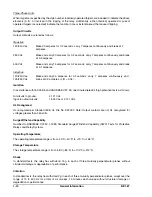
MODEL AND STYLE NUMBER
Style Number Identification Chart
BE1-67 Phase Directional Overcurrent Relay electrical characteristics and operational features are defined
by a combination of letters and numbers that make up the style number. Refer to Figure 1-9 for the Style
Number Identification Chart. Model numbers BE1-67 designate the relay as a Basler Electric, Class 100,
Phase Directional Overcurrent Relay. The model number together with the style number describes the options
included in a specific device and appear on the front panel, drawout cradle and inside the case assembly.
Upon receipt of a relay, be sure to check the style number against the requisition and the packing list to ensure
that they agree.
Figure 1-9. Style Number Identification Chart
Summary of Contents for BE1-67
Page 23: ...BE1 67 General Information 1 17 Figure 1 13 Timing Type B2 Long Inverse Drawing Number 99 0931...
Page 26: ...1 20 General Information BE1 67 Figure 1 16 Timing Type B5 Inverse Drawing Number 99 0929...
Page 27: ...BE1 67 General Information 1 21 Figure 1 17 Timing Type B6 Very Inverse Drawing Number 99 0928...
Page 39: ...2 6 Human Machine Interface BE1 67 Figure 2 3 Location of Assemblies Controls and Indicators...
Page 47: ...4 2 Installation BE1 67 Figure 4 1 Outline Dimensions Front View...
Page 48: ...BE1 67 Installation 4 3 Figure 4 2 Outline Dimensions Rear View...
Page 49: ...4 4 Installation BE1 67 Figure 4 3 Outline Dimensions Side View Semi Flush Mounting...
Page 50: ...BE1 67 Installation 4 5 Figure 4 4 Outline Dimensions Side View Projection Mounting...
Page 51: ...4 6 Installation BE1 67 Figure 4 5 Panel Drilling Diagram Semi Flush Mounting...
Page 52: ...BE1 67 Installation 4 7 Figure 4 6 Panel Drilling Diagram Projection Mounting...
Page 54: ...BE1 67 Installation 4 9 Figure 4 8 Single Phase AC Connections...
Page 55: ...4 10 Installation BE1 67 Figure 4 9 Three Phase AC Connections...
Page 56: ...BE1 67 Installation 4 11 Figure 4 10 BE1 67 Single Phase Internal Connection Diagram...
Page 57: ...4 12 Installation BE1 67 Figure 4 11 BE1 67 Three Phase Internal Connection Diagram...
Page 62: ...BE1 67 Testing 5 5 Figure 5 3 Blank Polar Graph Form Figure 5 4 Blank Polar Graph Form...