


Table 2-1. BE1-67 Controls and Indicators (refer to Figures 2-1, 2-2 and 2-3) - continued
Locator
Control Or Indicator
Function
BE1-67
Human-Machine Interface
2-5
CAUTION
This switch must be in the normal (
N
) position for proper
operation of the relay.
P
N/T
(
N
ormal/
T
est) Switch
This slide switch (shown in Figure 2-3) is mounted on the side of
the digital board. This permits a technician to access a series of
stored diagnostic routines to validate the calibration of the relay
and to test and troubleshoot the device on the bench.
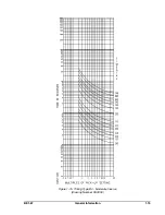
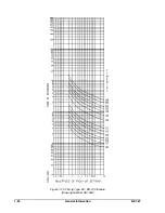
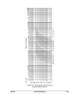
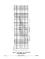
Table 2-2. Timing Curve Selection
Timing Type
Selector
Position
Ref. Figure
Number
Bl Short Inverse
3
1-12
B2 Long Inverse
1
1-13
B3 Definite Time
5
1-14
B4 Moderately Inverse
2
1-15
B5 Inverse
4
1-16
B6 Very Inverse
6
1-17
B7 Extremely Inverse
7
1-18
E2 BS142 Long Inverse
8
1-19
E4 BS142 Inverse (1.3 sec)
9
1-20
E BS142 Inverse (2.9 sec)
A
1-21
E6 BS142 Very Inverse
B
1-22
E7 BS142 Extremely Inverse
C, D, E, F
1-23
Summary of Contents for BE1-67
Page 23: ...BE1 67 General Information 1 17 Figure 1 13 Timing Type B2 Long Inverse Drawing Number 99 0931...
Page 26: ...1 20 General Information BE1 67 Figure 1 16 Timing Type B5 Inverse Drawing Number 99 0929...
Page 27: ...BE1 67 General Information 1 21 Figure 1 17 Timing Type B6 Very Inverse Drawing Number 99 0928...
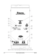
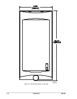
Page 39: ...2 6 Human Machine Interface BE1 67 Figure 2 3 Location of Assemblies Controls and Indicators...
Page 47: ...4 2 Installation BE1 67 Figure 4 1 Outline Dimensions Front View...
Page 48: ...BE1 67 Installation 4 3 Figure 4 2 Outline Dimensions Rear View...
Page 49: ...4 4 Installation BE1 67 Figure 4 3 Outline Dimensions Side View Semi Flush Mounting...
Page 50: ...BE1 67 Installation 4 5 Figure 4 4 Outline Dimensions Side View Projection Mounting...
Page 51: ...4 6 Installation BE1 67 Figure 4 5 Panel Drilling Diagram Semi Flush Mounting...
Page 52: ...BE1 67 Installation 4 7 Figure 4 6 Panel Drilling Diagram Projection Mounting...
Page 54: ...BE1 67 Installation 4 9 Figure 4 8 Single Phase AC Connections...
Page 55: ...4 10 Installation BE1 67 Figure 4 9 Three Phase AC Connections...
Page 56: ...BE1 67 Installation 4 11 Figure 4 10 BE1 67 Single Phase Internal Connection Diagram...
Page 57: ...4 12 Installation BE1 67 Figure 4 11 BE1 67 Three Phase Internal Connection Diagram...
Page 62: ...BE1 67 Testing 5 5 Figure 5 3 Blank Polar Graph Form Figure 5 4 Blank Polar Graph Form...