


1-12
General Information
BE1-67
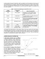
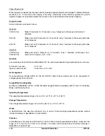
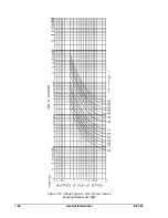
Figure 1-11. Characteristic Angle
Pickup Accuracy
The setting of the relay is repeatable within ±2 percent.
Dropout Ratio
The dropout ratio is better than 92 percent of the established pickup level.
Voltage Sensing Inputs
The continuous rating of these inputs are 240 Vac.
Voltage Sensing Burden
The voltage sensing burden is greater than 25 kilo-ohm at 120 Vac per input.
Directional Unit
The polarizing for the directional unit is derived by the phase relationship between the measured phase current
(A) and the sensed quadrature voltage (b-c). The directional element defines a region as shown in Figure 1-11
for which tripping will be allowed. The characteristic angle of the relay is defined as the angle between I
z
and
its ordinate, I. Note that I
z
is normal to the characteristic boundary. Resolution of direction requires less than
1 cycle.
Sensitivity
Proper directional decisions are assured when the current applied to the relay exceeds 25% of TAP value and
the voltage exceeds 1.0 Vac at the setting of the characteristic angle. When polarizing voltage is less than the
1.0 Vac threshold, relay operation will be inhibited.
Characteristic Angle
Adjustment
The BE1-67 is available with two types of adjustment for the characteristic angle.
Summary of Contents for BE1-67
Page 23: ...BE1 67 General Information 1 17 Figure 1 13 Timing Type B2 Long Inverse Drawing Number 99 0931...
Page 26: ...1 20 General Information BE1 67 Figure 1 16 Timing Type B5 Inverse Drawing Number 99 0929...
Page 27: ...BE1 67 General Information 1 21 Figure 1 17 Timing Type B6 Very Inverse Drawing Number 99 0928...
Page 39: ...2 6 Human Machine Interface BE1 67 Figure 2 3 Location of Assemblies Controls and Indicators...
Page 47: ...4 2 Installation BE1 67 Figure 4 1 Outline Dimensions Front View...
Page 48: ...BE1 67 Installation 4 3 Figure 4 2 Outline Dimensions Rear View...
Page 49: ...4 4 Installation BE1 67 Figure 4 3 Outline Dimensions Side View Semi Flush Mounting...
Page 50: ...BE1 67 Installation 4 5 Figure 4 4 Outline Dimensions Side View Projection Mounting...
Page 51: ...4 6 Installation BE1 67 Figure 4 5 Panel Drilling Diagram Semi Flush Mounting...
Page 52: ...BE1 67 Installation 4 7 Figure 4 6 Panel Drilling Diagram Projection Mounting...
Page 54: ...BE1 67 Installation 4 9 Figure 4 8 Single Phase AC Connections...
Page 55: ...4 10 Installation BE1 67 Figure 4 9 Three Phase AC Connections...
Page 56: ...BE1 67 Installation 4 11 Figure 4 10 BE1 67 Single Phase Internal Connection Diagram...
Page 57: ...4 12 Installation BE1 67 Figure 4 11 BE1 67 Three Phase Internal Connection Diagram...
Page 62: ...BE1 67 Testing 5 5 Figure 5 3 Blank Polar Graph Form Figure 5 4 Blank Polar Graph Form...