


5-12
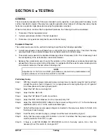
Testing
BE1-67
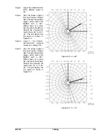
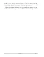
Figure 5-13. Limited Region Of
Operation Setting
Refer to Figure 5-13.
Where:
Phase
I
=
phase of the applied current relative to the applied voltage
$
=
desired LIMITED REGION OF OPERATION setting
+ angle =
leading current
- angle =
lagging current
Step
5.
Slowly rotate the LIMITED REGION
OF
OPERATION control CCW until the INHIBIT LED
just illuminates.
Verifying Relay Settings
A verification of the directional setting should now be
performed.
Step 6.
Vary the applied current phase angle through 360°
and record the angle values at which the
appropriate phase INHIBIT LED turns ON and
OFF. Plot the results on a polar coordinate graph
for future reference.
SETTING THE RELAY - AN EXAMPLE
One method of setting the relay is described here. There are other methods that may be used as well. All
methods involve similar steps and equipment.
Example Defined
Before the relay can be set, the required settings need to be defined. A typical example follows.
Time overcurrent pickup:
5.7 A
Curve shape:
Very inverse
Time delay setting:
0.6 second at 28.5 A
Instantaneous overcurrent pickup:
39.9 A
Line impedance angle:
60°
Limited range of operation:
B = 45°
The relay that has been selected for this application is a BE1-67, style number B1E-Z2Y-B1N6F.
Before applying sensing inputs to the relay, a few adjustments are necessary.
Step 1.
Since the relay includes the Z2 timing option, the characteristic curve needs to be selected. This
is accomplished by removing the front panel and adjusting the TIME OVERCURRENT
CHARACTERISTIC CURVE SELECTOR switch to position 6. (See Very Inverse, Table 1-4.)
Step 2.
Because the time overcurrent pickup is 5.7 amperes, the sensing current input for the relay will
need to be connected for the HIGH range. Adjust the TAP RANGE plate on the front panel to
display the word HIGH. Verify that the current connections to the relay are on terminals 7 and 8
(phase A), 14 and 15 (phase B), and 17 and 18 (phase C). Terminals 9, 13 and 16 should not be
connected.
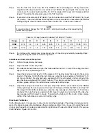
Step 3.
Calculate the ratio of the instantaneous overcurrent pickup setting to the time overcurrent pickup
setting.
In this example, the ratio is 39.9 ÷ 5.7 = 7. (This ratio is used in Step 2,
Setting The Pickups
.)
Summary of Contents for BE1-67
Page 23: ...BE1 67 General Information 1 17 Figure 1 13 Timing Type B2 Long Inverse Drawing Number 99 0931...
Page 26: ...1 20 General Information BE1 67 Figure 1 16 Timing Type B5 Inverse Drawing Number 99 0929...
Page 27: ...BE1 67 General Information 1 21 Figure 1 17 Timing Type B6 Very Inverse Drawing Number 99 0928...
Page 39: ...2 6 Human Machine Interface BE1 67 Figure 2 3 Location of Assemblies Controls and Indicators...
Page 47: ...4 2 Installation BE1 67 Figure 4 1 Outline Dimensions Front View...
Page 48: ...BE1 67 Installation 4 3 Figure 4 2 Outline Dimensions Rear View...
Page 49: ...4 4 Installation BE1 67 Figure 4 3 Outline Dimensions Side View Semi Flush Mounting...
Page 50: ...BE1 67 Installation 4 5 Figure 4 4 Outline Dimensions Side View Projection Mounting...
Page 51: ...4 6 Installation BE1 67 Figure 4 5 Panel Drilling Diagram Semi Flush Mounting...
Page 52: ...BE1 67 Installation 4 7 Figure 4 6 Panel Drilling Diagram Projection Mounting...
Page 54: ...BE1 67 Installation 4 9 Figure 4 8 Single Phase AC Connections...
Page 55: ...4 10 Installation BE1 67 Figure 4 9 Three Phase AC Connections...
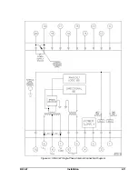
Page 56: ...BE1 67 Installation 4 11 Figure 4 10 BE1 67 Single Phase Internal Connection Diagram...
Page 57: ...4 12 Installation BE1 67 Figure 4 11 BE1 67 Three Phase Internal Connection Diagram...
Page 62: ...BE1 67 Testing 5 5 Figure 5 3 Blank Polar Graph Form Figure 5 4 Blank Polar Graph Form...