Basler BE1-67 Instruction Manual Download Page 45

3-6

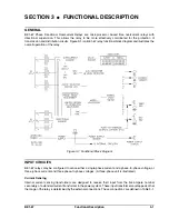
Functional Description

BE1-67

Push-to-Energize Output Contacts

If option 2-C has been selected, a small pushbutton switch is included for the time overcurrent functions and
if present for the instantaneous function. Each switch when depressed will energize the corresponding output
relay for testing purposes. To prevent accidental operation of these switches, they have been recessed behind
the front panel of the relay and are accessed by inserting a thin non-conducting rod through access holes in
the panel.

Appropriate power must be applied to terminals 3 and 4 (the relay power supply) for these pushbuttons to
operate the output relays. However, it is not necessary to apply currents and voltages to the sensing inputs
of the relay for these switches to function.

Power Supply Status Output

The power supply status output relay (option 3-3 and 3-4) has normally closed output contacts. This relay is
energized by the presence of nominal voltage at the output of the power supply. Normal operating voltage then
keeps the relay continuously energized and the contacts open. However, if the power supply voltage falls
below requirements, the power supply status output relay will de-energize and close the contacts.

A shorting bar is included in the relay case so that the status output terminals can provide a remote indication
that the subject relay has been withdrawn from the case or taken out of service by removing the connection
plug.

This output is not associated with any magnetically latched target. The POWER LED on the relay front panel
provides a visual indication of normal operating status of the power supply.

TARGET INDICATOR CIRCUITS

When the TARGET option is specified as either an A or a B, magnetically latched target indicators are
included within the relay. Targets are provided for the TIME overcurrent and the optional INST (instantaneous)
overcurrent functions. These targets may be actuated by either of two methods as defined by the style number
and explained in the following paragraphs.

Type A targets (referred to as INTERNALLY OPERATED) are operated by an internal driver circuit that is
actuated by a signal from the relay internal logic circuits. This type of target is tripped regardless of the current
level flowing through the output relay contacts. It is the only type of target that can be supplied if the output
contacts are specified as normally closed (output F).

Type B targets (referred to as CURRENT OPERATED) are operated when a minimum of 0.2 ampere flows
through the relay output contacts. To accomplish this, a special reed relay is placed in series with the output
contacts to provide the necessary signal to the target indicator. (The series impedance of the reed relay is less
than 0.1 ohm.)

Each target indicator is visible on the front panel of the relay with the cover in place. When operated, the disc
in the target changes from black to red and is magnetically latched in this position. To reset the target after
an abnormal system condition has been cleared, manually raise the target reset level on the front of the relay
or in the lower portion of the cover.

When targets are specified on single-phase relays (sensing input type A) only TIME and INST (instantaneous)
FUNCTION targets are provided. These targets may be either type A or type B.

Three-phase (Sensing Input type B) relays are supplied, when specified, with FUNCTION (TIME and INST)
targets and ELEMENT targets (A, B, C). The FUNCTION targets are either type A or type B as specified by
the style number. The ELEMENT targets are always type A (internally operated) targets.

Summary of Contents for BE1-67

Page 1: ...INSTRUCTION MANUAL FOR PHASE DIRECTIONAL OVERCURRENT RELAY BE1 67 Publication 9 1709 00 990 Revision G 05 2003...

Page 2: ...RES PRESENTED IN THIS MANUAL INTRODUCTION This manual provides information concerning the operation and installation of the BE1 67 Phase Directional Overcurrent Relay To accomplish this the following...

Page 3: ...er Electric Co Highland IL 62249 May 2003 It is not the intention of this manual to cover all details and variations in equipment nor does this manual provide data for every possible contingency regar...

Page 4: ...age 5 13 added the Basler publication where the B6 Very Inverse drawing can be found Updated the manual style throughout Rev F 11 95 15426 Changed Specifications for Isolation in Section I and Dielect...

Page 5: ...tio 1 10 Timing Characteristics 1 11 Time Delay Accuracy 1 11 Instantaneous Overcurrent 1 11 Voltage Sensing Inputs 1 12 Voltage Sensing Burden 1 12 Directional Unit 1 12 Sensitivity 1 12 Characterist...

Page 6: ...uipment Required 5 1 Preliminary Setup 5 1 VERIFICATION TESTING 5 3 Time Overcurrent Pickup Test 5 3 Instantaneous Overcurrent Pickup Test 5 4 Directional Verification 5 4 TIMING CURVE VERIFICATION 5...

Page 7: ...y the relay will pickup time out and trip The angle of maximum sensitivity for the relay is also adjustable to allow the directional characteristic to be matched to the line and system conditions Figu...

Page 8: ...with other relays B6 E6 Very Inverse B7 E7 Extremely Inverse If the supply to the protected portion of the system is constant and if the magnitude of the fault current is determined primarily by the l...

Page 9: ...Infeed Condition During a period of abnormally low system voltage leading power factor current above relay pickup can flow in the non trip direction of a line Probable current sources are outlying cap...

Page 10: ...of directional overcurrent relays on a group of interconnected distribution substations fed from a common source In this example non directional overcurrent relays 51 are used to protect the lines lea...

Page 11: ...Two Sources SAMPLE APPLICATION CALCULATIONS In this sample illustrated by Figure 1 7 a three phase 60 hertz BE1 67 relay is used at breaker position A Assumed options for the relay include switch sele...

Page 12: ...tor represents a margin of safety Analysis Of Fault L In Figure 1 7 assume the following fault L currents IA L 3 000 amperes at an angle of 65 degrees ID L 6 400 amperes at an angle of 60 degrees Base...

Page 13: ...seen by IA also allows the directional instantaneous unit to be set to trip for high current close in faults Directional Instantaneous Setting 4 600 1 400 0 8 margin 9 2 amperes Figure 1 8 Coordinatio...

Page 14: ...e MODEL AND STYLE NUMBER Style Number Identification Chart BE1 67 Phase Directional Overcurrent Relay electrical characteristics and operational features are defined by a combination of letters and nu...

Page 15: ...ts because they confirm that a current signal flowed in the output circuit and resulted in a trip However as the style chart notes current operated targets are only available when a normally open cont...

Page 16: ...switch and TAP CAL adjustment A TAP RANGE plate is provided on the front panel to define the external connections and the range of adjustment available when the unit is installed in the protection pa...

Page 17: ...rately Inverse 99 0930 4 B5 Inverse 99 0929 6 B6 Very Inverse 99 0928 7 B7 Extremely Inverse 99 0927 8 E2 Long Inverse BS 142 99 1093 9 E4 Inverse 1 3 Sec BS 142 99 1094 A E5 Inverse 2 9 Sec BS 142 99...

Page 18: ...nd the sensed quadrature voltage b c The directional element defines a region as shown in Figure 1 11 for which tripping will be allowed The characteristic angle of the relay is defined as the angle b...

Page 19: ...nge Burden at Nominal K 48 Vdc 24 to 60 Vdc 7 0 W J 125 Vdc 120 Vac 62 to 150 Vdc 90 to 132 Vac 10 0 W 20 0 VA L 24 Vdc 12 to 32 Vdc 7 0 W Y 48 Vdc 125 Vdc 24 to 60 Vdc 62 to 150 Vdc 7 0 W 7 5 W Z 250...

Page 20: ...04 Isolation In accordance with IEC 255 5 and ANSI IEEE C37 90 one minute dielectric high potential tests as follows All circuits to ground 2 121 Vdc Input to output circuits 1 500 Vac or 2 121 Vdc U...

Page 21: ...der full size drawings of these characteristic curves contact Customer Service Department of the Power Systems Group Basler Electric and request publication number 9 1907 00 999 This publication conta...

Page 22: ...1 16 General Information BE1 67 Figure 1 12 Timing Type B1 Short Inverse Drawing Number 99 0932...

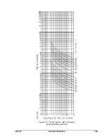
Page 23: ...BE1 67 General Information 1 17 Figure 1 13 Timing Type B2 Long Inverse Drawing Number 99 0931...

Page 24: ...1 18 General Information BE1 67 Figure 1 14 Timing Type B3 Definite Time Drawing Number 99 0933...

Page 25: ...BE1 67 General Information 1 19 Figure 1 15 Timing Type B4 Moderate Inverse Drawing Number 99 0930...

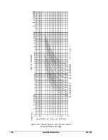
Page 26: ...1 20 General Information BE1 67 Figure 1 16 Timing Type B5 Inverse Drawing Number 99 0929...

Page 27: ...BE1 67 General Information 1 21 Figure 1 17 Timing Type B6 Very Inverse Drawing Number 99 0928...

Page 28: ...1 22 General Information BE1 67 Figure 1 18 Timing Type B7 Extremely Inverse Drawing Number 99 0927...

Page 29: ...BE1 67 General Information 1 23 Figure 1 19 Timing Type E2 BS 142 Long Inverse Drawing Number 99 1093...

Page 30: ...1 24 General Information BE1 67 Figure 1 20 Timing Type E4 BS 132 Inverse Drawing Number 99 1094...

Page 31: ...BE1 67 General Information 1 25 Figure 1 21 Timing Type E5 BS 142 Inverse Drawing Number 99 1095...

Page 32: ...1 26 General Information BE1 67 Figure 1 22 Timing Type E6 BS 142 Very Inverse Drawing Number 99 1096...

Page 33: ...BE1 67 General Information 1 27 Figure 1 23 Timing Type E7 BS 142 Extremely Inverse Drawing Number 99 1097...

Page 34: ...ckup of the relay is based on the setting of the TAP selector switch The setting for the time overcurrent function is the value defined by the switch position A to J and the external connections HIGH...

Page 35: ...2 2 Human Machine Interface BE1 67 Figure 2 1 BE1 67 Three Phase Relay With Characteristic Angle Control Knob...

Page 36: ...BE1 67 Human Machine Interface 2 3 Figure 2 2 BE1 67 Three Phase Relay With Characteristic Angle and Limited Region Of Operation...

Page 37: ...is control is in the full clockwise position the setting of the TIME overcurrent element s is within 5 of the selected tap setting As the control is rotated counterclockwise the pickup value of the el...

Page 38: ...technician to access a series of stored diagnostic routines to validate the calibration of the relay and to test and troubleshoot the device on the bench Table 2 2 Timing Curve Selection Timing Type...

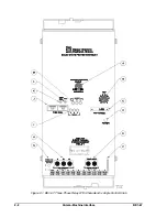
Page 39: ...2 6 Human Machine Interface BE1 67 Figure 2 3 Location of Assemblies Controls and Indicators...

Page 40: ...eration of the relay Figure 3 1 Functional Block Diagram INPUT CIRCUITS BE1 67 relays may be configured to sense either a single phase current and a phase to phase voltage or three phase currents and...

Page 41: ...0 LOW 0 75 1 0 1 5 1 75 2 25 2 5 3 0 3 25 3 75 4 0 The TAP CAL control provides a means of continuous adjustment between a selected setting of the TAP SELECT and the next lower setting When the TAP S...

Page 42: ...s do not meet the criteria of the directional element an inhibit signal is output This signal illuminates the appropriate PHASE INHIBIT LED on the relay front panel and prevents the operation of the t...

Page 43: ...monitored by the relay LED s may be used to determine the actual pickup setting of the relay during testing POWER LED s A red LED lights when the relay power supply is functioning This provides a fro...

Page 44: ...ulfills many of the logic and signal processing functions described in the following paragraphs and performs all of the time overcurrent computations Multiplexor The multiplexor sequentially switches...

Page 45: ...cified as either an A or a B magnetically latched target indicators are included within the relay Targets are provided for the TIME overcurrent and the optional INST instantaneous overcurrent function...

Page 46: ...alse tripping when removing connection plugs always remove the lower connection plug first To avoid false tripping when inserting connection plugs always insert the lower connection plug last 3 BE1 67...

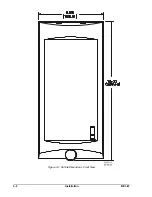
Page 47: ...4 2 Installation BE1 67 Figure 4 1 Outline Dimensions Front View...

Page 48: ...BE1 67 Installation 4 3 Figure 4 2 Outline Dimensions Rear View...

Page 49: ...4 4 Installation BE1 67 Figure 4 3 Outline Dimensions Side View Semi Flush Mounting...

Page 50: ...BE1 67 Installation 4 5 Figure 4 4 Outline Dimensions Side View Projection Mounting...

Page 51: ...4 6 Installation BE1 67 Figure 4 5 Panel Drilling Diagram Semi Flush Mounting...

Page 52: ...BE1 67 Installation 4 7 Figure 4 6 Panel Drilling Diagram Projection Mounting...

Page 53: ...in damage to the relay Be sure to check the model and style number of the relay before connecting and energizing the particular relay Except as noted above connections should be made with minimum wir...

Page 54: ...BE1 67 Installation 4 9 Figure 4 8 Single Phase AC Connections...

Page 55: ...4 10 Installation BE1 67 Figure 4 9 Three Phase AC Connections...

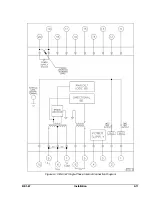
Page 56: ...BE1 67 Installation 4 11 Figure 4 10 BE1 67 Single Phase Internal Connection Diagram...

Page 57: ...4 12 Installation BE1 67 Figure 4 11 BE1 67 Three Phase Internal Connection Diagram...

Page 58: ...rrent element c Because the current levels used to verify the operation of the instantaneous overcurrent element may exceed the continuous current rating of the relay it is suggested that the current...

Page 59: ...t the voltage source to 120 Vac at a phase angle of 0 Adjust the input current source to 1 0 ampere LOW range or 3 0 ampere HIGH range and at a phase angle of 1 Then starting from the maximum CW posit...

Page 60: ...erforming the preliminary setup adjust the input voltage source for 120 Vac at a phase angle of 0 Step 2 Adjust the input current source for 0 5 ampere LOW range or 1 5 amperes HIGH range at a phase a...

Page 61: ...d option 1 3 adjust the voltage source to apply 120 Vac at a phase angle of 0 Step 4 Adjust the sensing current level for 0 75 amperes at 90 leading Apply this current to the sensing input s of the re...

Page 62: ...BE1 67 Testing 5 5 Figure 5 3 Blank Polar Graph Form Figure 5 4 Blank Polar Graph Form...

Page 63: ...or 3 0 amperes HIGH range at a phase angle of 90 90 leading Result The INHIBIT LED indicator should be extinguished and the appropriate phase timing LED OFF If not the current or voltage connections a...

Page 64: ...tate the LIMITED REGION OF O P E R A T I O N potentiometer fully CCW Step 8 Vary the phase angle of the input current through 360 and record the phase angles within which the INHIBIT LED is OFF When s...

Page 65: ...n a 3 phase unit If not current or voltage connections are reversed and should be corrected Step 5 Vary the phase angle of the input current through 360 and record the phase angles at which the INHIBI...

Page 66: ...a straight line through the origin from a 60 to 120 5 This plot defines the trip region as shown in Figure 5 10 Step 10 A d j u s t t h e C H A R ACTERISTIC ANGLE control to a setting of 75 Step 11 V...

Page 67: ...hever is greater within the values shown graphically on the published characteristic curves Verification of the timing may be performed at a low current level for convenience Connect the relay as show...

Page 68: ...controls options 3 1 3 3 3 5 or 3 6 perform the following steps Step 1 Perform the preliminary setup procedures at the beginning of this section Step 2 With the CHARACTERISTIC ANGLE set to minimum app...

Page 69: ...urve shape Very inverse Time delay setting 0 6 second at 28 5 A Instantaneous overcurrent pickup 39 9 A Line impedance angle 60 Limited range of operation B 45 The relay that has been selected for thi...

Page 70: ...rotate the TAP CAL control CCW until the TIMING LED lights Time overcurrent pickup is now set for 5 7 amperes and the instantaneous overcurrent pickup is set for 39 9 amperes Step 10 Reduce the sensin...

Page 71: ...ol CCW from maximum setting until the INHIBIT LED just turns OFF Step 3 Vary the applied current phase angle through 360 and record the angle values at which the appropriate phase INHIBIT LED turns ON...

Page 72: ...of the original components Where special components are involved Basler Electric part numbers may be obtained from the number stamped on the component or assembly the schematic or parts list These par...

Page 73: ...y internal circuitry The ten fingers on the red side of the test plug are connected to the outer binding posts red thumb nuts and to the relay case terminals When testing circuits connected to the bot...

Reviews: