


BE1-67
General Information
1-11
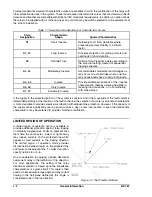
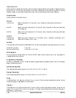
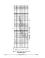
Figure 1-10. Typical Instantaneous Response Time
Timing Characteristics
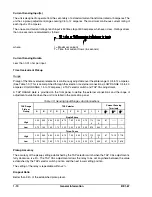
The relay includes a choice of characteristics. A two-character designation within the style number defines
the timing characteristic. (See Table 1-4.)
Table 1-4. Characteristic Curves and Switch Positions
Switch Position
For Z2 Option
Characteristic
Curve
Characteristic Description
Drawing
Number
3
B1
Short Inverse
99-0932
1
B2
Long Inverse
99-0931
5
B3
Definite
99-0933
2
B4
Moderately Inverse
99-0930
4
B5
Inverse
99-0929
6
B6
Very Inverse
99-0928
7
B7
Extremely Inverse
99-0927
8
E2
Long Inverse (BS 142)
99-1093
9
E4
Inverse (1.3 Sec.) (BS 142)
99-1094
A
E5
Inverse (2.9 Sec.) (BS 142)
99-1095
B
E6
Very Inverse (BS 142)
99-1096
C, D, E, F
E7
Extremely Inverse (BS 142)
99-1097
Time Delay Accuracy
The time delay of the time overcurrent element is within ±5 percent or 50 milliseconds (whichever is greater)
of the characteristic curves for any combination of TIME DIAL, TAP and TAP CAL settings at 25°C.
Instantaneous Overcurrent
Pickup Range
Continuously adjustable over the range of one to 40 times the pickup setting established for the time
overcurrent element.
Response Time
Summary of Contents for BE1-67
Page 23: ...BE1 67 General Information 1 17 Figure 1 13 Timing Type B2 Long Inverse Drawing Number 99 0931...
Page 26: ...1 20 General Information BE1 67 Figure 1 16 Timing Type B5 Inverse Drawing Number 99 0929...
Page 27: ...BE1 67 General Information 1 21 Figure 1 17 Timing Type B6 Very Inverse Drawing Number 99 0928...
Page 39: ...2 6 Human Machine Interface BE1 67 Figure 2 3 Location of Assemblies Controls and Indicators...
Page 47: ...4 2 Installation BE1 67 Figure 4 1 Outline Dimensions Front View...
Page 48: ...BE1 67 Installation 4 3 Figure 4 2 Outline Dimensions Rear View...
Page 49: ...4 4 Installation BE1 67 Figure 4 3 Outline Dimensions Side View Semi Flush Mounting...
Page 50: ...BE1 67 Installation 4 5 Figure 4 4 Outline Dimensions Side View Projection Mounting...
Page 51: ...4 6 Installation BE1 67 Figure 4 5 Panel Drilling Diagram Semi Flush Mounting...
Page 52: ...BE1 67 Installation 4 7 Figure 4 6 Panel Drilling Diagram Projection Mounting...
Page 54: ...BE1 67 Installation 4 9 Figure 4 8 Single Phase AC Connections...
Page 55: ...4 10 Installation BE1 67 Figure 4 9 Three Phase AC Connections...
Page 56: ...BE1 67 Installation 4 11 Figure 4 10 BE1 67 Single Phase Internal Connection Diagram...
Page 57: ...4 12 Installation BE1 67 Figure 4 11 BE1 67 Three Phase Internal Connection Diagram...
Page 62: ...BE1 67 Testing 5 5 Figure 5 3 Blank Polar Graph Form Figure 5 4 Blank Polar Graph Form...