


5-10
Testing
BE1-67
TIMING CURVE VERIFICATION
There are many timing characteristics available for BE1-67 relays. Table 5-2 provides two checkpoints for
each of the twelve timing characteristic curve types.
The characteristic included within the relay is defined in the style number by a two-character code. If this code
is B1 to B7, E2, or E4 to E7, only one characteristic can be tested. If the code is Z2, the characteristic desired
will need to be selected by the TIME OVERCURRENT CHARACTERISTIC CURVE SELECTOR switch
located behind the front panel of the relay. (Refer to Figure 2-3 for switch location.) Table 5-2 defines the
position of this selector for the desired characteristic.
Table 5-2. Expected Timing Values At Five Times Pickup
TIMING
TYPE
Z2 Option
Selector
Position
Expected Times at Indicated Time Dial Setting* (in seconds)
00
10
B1
3
0.066
0.194
B2
1
0.587
3.41
B3
5
0.103
0.494
B4
2
0.168
0.875
B5
4
0.149
0.722
B6
6
0.126
0.551
B7
7
0.195
1.011
E2
8
1.56
9.06
E4
9
0.13
0.54
E5
A
0.233
1.190
E6
B
0.16
0.77
E7
C, D, E, F
0.13
0.48
NOTE:
Accuracy, with the TAP CAL control rotated fully CW, is ±5% or 50 milliseconds (whichever is
greater) within the values shown graphically on the published characteristic curves.
Verification of the timing may be performed at a low current level for convenience. Connect the relay as shown
in Figure 5-1 or 5-2. In the following steps, the timing will be measured from the point that the sensed current
is applied until the output contact is energized. The equipment to accomplish this task will need to step from
0 to 3.75 amperes (if the relay is connected for LOW range) or 11.25 amperes (if the relay is connected for
HIGH range).
Step 1.
Set the TAP SELECT switch to position A and rotate the TAP CAL control fully CW. Rotate the
INST control (if included) fully CW. Adjust the TIME DIAL to 00. Set the LIMITED REGION OF
OPERATION control (if so equipped) to the maximum (fully CW) position.
Step 2.
Adjust the source current for 0.75 amperes (LOW range) or 2.25 amperes (HIGH range) and apply
this current to the sensing input(s) of the relay. (See Figure 5-1 or 5-2.) Voltage will also need to
be applied to the sensing input of the directional element for this test. The phase angle between the
current and voltage should be adjusted so that the TIMING LED lights when the pickup current is
applied. Adjust the TAP CAL control (if required) such that the TIMING LIGHT is ON. This sets the
pickup of the relay for the following steps.
Summary of Contents for BE1-67
Page 23: ...BE1 67 General Information 1 17 Figure 1 13 Timing Type B2 Long Inverse Drawing Number 99 0931...
Page 26: ...1 20 General Information BE1 67 Figure 1 16 Timing Type B5 Inverse Drawing Number 99 0929...
Page 27: ...BE1 67 General Information 1 21 Figure 1 17 Timing Type B6 Very Inverse Drawing Number 99 0928...
Page 39: ...2 6 Human Machine Interface BE1 67 Figure 2 3 Location of Assemblies Controls and Indicators...
Page 47: ...4 2 Installation BE1 67 Figure 4 1 Outline Dimensions Front View...
Page 48: ...BE1 67 Installation 4 3 Figure 4 2 Outline Dimensions Rear View...
Page 49: ...4 4 Installation BE1 67 Figure 4 3 Outline Dimensions Side View Semi Flush Mounting...
Page 50: ...BE1 67 Installation 4 5 Figure 4 4 Outline Dimensions Side View Projection Mounting...
Page 51: ...4 6 Installation BE1 67 Figure 4 5 Panel Drilling Diagram Semi Flush Mounting...
Page 52: ...BE1 67 Installation 4 7 Figure 4 6 Panel Drilling Diagram Projection Mounting...
Page 54: ...BE1 67 Installation 4 9 Figure 4 8 Single Phase AC Connections...
Page 55: ...4 10 Installation BE1 67 Figure 4 9 Three Phase AC Connections...
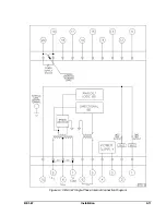
Page 56: ...BE1 67 Installation 4 11 Figure 4 10 BE1 67 Single Phase Internal Connection Diagram...
Page 57: ...4 12 Installation BE1 67 Figure 4 11 BE1 67 Three Phase Internal Connection Diagram...
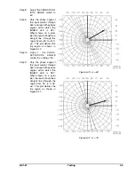
Page 62: ...BE1 67 Testing 5 5 Figure 5 3 Blank Polar Graph Form Figure 5 4 Blank Polar Graph Form...