


BE1-67
Testing
5-11
NOTE
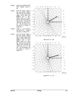
Set the CHARACTERISTIC ANGLE by adjusting one end point of the 180° trip region. In
Figure 5-12, the test current lags the CHARACTERISTIC ANGLE by 90°.
Figure 5-12. Directional Setting
Step 3.
Connect a counter to monitor the time interval from initiation of the timing condition to the output
transition.
Step 4.
Switch the sensing current from 0.0 amperes to 3.75 amperes (LOW range) or 11.25 amperes
(HIGH range). (This is 5 times the level set in step 2.) Monitor the time required to energize the
output contacts and compare that time with the value in Table 5-2.
Step 5.
Adjust the TIME DIAL to 10 and repeat step 4.
This completes relay verification testing.
DIRECTIONAL SETTING PROCEDURE
Characteristic Angle
For switch selectable controls (options 3-2 or 3-4), simply turn the control to the desired setting in accordance
with the markings on the front panel.
For potentiometer controls (options 3-1, 3-3, 3-5, or 3-6), perform the following steps:
Step 1.
Perform the preliminary setup procedures at the beginning of this section.
Step 2.
With the CHARACTERISTIC ANGLE set to minimum, apply a voltage input of 120 Vac at a phase
angle of 0° and a current input of 1.0 ampere (LOW range) or 3.0 amperes (HIGH range) at a
lagging phase angle equal to the desired CHARACTERISTIC ANGLE setting. The appropriate
phase INHIBIT LED should be ON.
Step 3.
Slowly rotate the CHARACTERISTIC ANGLE control
CW to the position where the appropriate phase
INHIBIT LED lights.
Legend For Figure 5-12
2
1 = Desired characteristic angle setting.
Since
2
1 =
2
2, apply I
TEST
at a lagging angle equal to the desired
characteristic angle setting.
Limited Region Of Operation
If the relay includes the LIMITED REGION OF OPERATION
option, perform the following steps. If this option is not included,
continue with
Verifying The Setting
.
Step 4.
Apply a voltage input of 120 Vac at a phase angle of
0° and a current input of 1.0 ampere (LOW range) or
3.0 amperes (HIGH range) at a phase angle defined
by the following equation.
Summary of Contents for BE1-67
Page 23: ...BE1 67 General Information 1 17 Figure 1 13 Timing Type B2 Long Inverse Drawing Number 99 0931...
Page 26: ...1 20 General Information BE1 67 Figure 1 16 Timing Type B5 Inverse Drawing Number 99 0929...
Page 27: ...BE1 67 General Information 1 21 Figure 1 17 Timing Type B6 Very Inverse Drawing Number 99 0928...
Page 39: ...2 6 Human Machine Interface BE1 67 Figure 2 3 Location of Assemblies Controls and Indicators...
Page 47: ...4 2 Installation BE1 67 Figure 4 1 Outline Dimensions Front View...
Page 48: ...BE1 67 Installation 4 3 Figure 4 2 Outline Dimensions Rear View...
Page 49: ...4 4 Installation BE1 67 Figure 4 3 Outline Dimensions Side View Semi Flush Mounting...
Page 50: ...BE1 67 Installation 4 5 Figure 4 4 Outline Dimensions Side View Projection Mounting...
Page 51: ...4 6 Installation BE1 67 Figure 4 5 Panel Drilling Diagram Semi Flush Mounting...
Page 52: ...BE1 67 Installation 4 7 Figure 4 6 Panel Drilling Diagram Projection Mounting...
Page 54: ...BE1 67 Installation 4 9 Figure 4 8 Single Phase AC Connections...
Page 55: ...4 10 Installation BE1 67 Figure 4 9 Three Phase AC Connections...
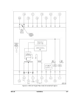
Page 56: ...BE1 67 Installation 4 11 Figure 4 10 BE1 67 Single Phase Internal Connection Diagram...
Page 57: ...4 12 Installation BE1 67 Figure 4 11 BE1 67 Three Phase Internal Connection Diagram...
Page 62: ...BE1 67 Testing 5 5 Figure 5 3 Blank Polar Graph Form Figure 5 4 Blank Polar Graph Form...