BARTINGTON INSTRUMENTS
Page 14 of 61 OM1800/26
Note:
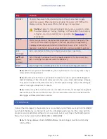
Assemble the gradiometer such that the arrows marked on the sensors are carefully
aligned to point in the direction in which the operator will walk. This will assist the
operator in pointing the arrows in the required direction during the set-up procedure. For a
single sensor the arrow should be aligned along the beam. The beam can then be pointed
in the appropriate direction during set up. Dual sensors should be mounted with the arrow
on each sensor at a right angle to the beam, with each arrow carefully aligned parallel to
the other.
Caution:
Do not plug or unplug the sensor cables while the data logger is on. Doing so can
affect the sensor adjustment, or cause data logger errors.
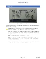
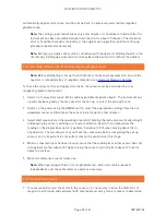
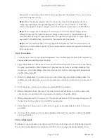
The data logger unit has a pair of fixing holes on the underside (Figure 7) for securing the unit to
the beam. The Grad601-1 single sensor gradiometer has the sensor and data logger mounted in
front of the operator and the battery box located at the end of the beam to give a balanced
assembly as shown in
Figure 3
.
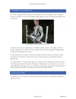
The Grad601-2 dual sensor gradiometer is carried with the beam across the front of the operator
with one sensor on each side as shown in
Figure 2
. The data logger is located with the controls
facing the operator and the battery mounted directly below it, and attached to the data logger
through the beam with two knurled captive screws.
To detach the battery from the datalogger, turn the two brass screws at the top of the battery
cassette. Ensure to hold the datalogger as it will become loose.
Should the cables need to be removed from the beam, the datalogger side of the cable can be fed
through the beam. To remove the right-hand side cable, the green/red push button will need to
be unscrewed.
Figure 7a: DL601 Data Logger underside.


