BARTINGTON INSTRUMENTS
Page 35 of 61 OM1800/26
with suitable ropes. It is also convenient to lay a rope along each traverse with 1m rope
markers on it to allow the operator to keep pace with the data logging.
17.3. Surveying at 1 line/m
A line spacing of 1m (
lines/m
set to 1 in
Survey Parameters
) is normally used and is sufficient to
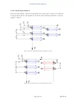
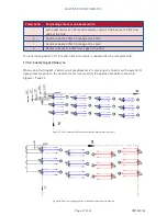
locate most archaeological features. A “trapeze” comprising two ropes spaced 1m apart, with
marks at 1m intervals along the ropes, will allow the operator to keep pace with the time bleeps.
For a single sensor, the operator should walk with the sensor over one trapeze line and return
with it over the other, as in Figure 15.
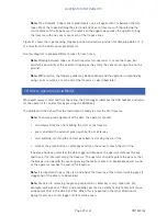
For a dual sensor, the right hand sensor is held over the trapeze lines as in Figure 16.
Note:
Mark the centre of the trapeze and the ropes along the start and end of the traverses
appropriately to allow the trapeze to be positioned correctly. If the centre of the trapeze
is marked then, for a single sensor gradiometer, mark the start and end traverse ropes
at intervals of 2m, with the first mark 1m from the edge of the Grid. For a dual sensor
gradiometer the intervals should be 4m with the first mark 2m from the edge of the Grid.
17.4. Surveying at 2 or 4 lines/m
The DL601 Data Logger software Version 5.7, and later, allows data to be collected with a line
spacing of 1, 2 or 4 lines/m for both single and dual sensor gradiometers. The line spacing is
therefore 1, 0.5 or 0.25m.
Using a Grad601-1 single sensor gradiometer, the situation is straightforward with the first line
being recorded at half the line space from the edge of the Grid and subsequent lines separated
by one line space. The pattern may be parallel or zigzag as selected in the
Set parameters
menu,
and the marking of ropes at the ends of traverse is straightforward. If using a 1m wide trapeze
as described above, the width of the trapeze should correspond to the line space selected when
using a Grad601-1 single sensor gradiometer.
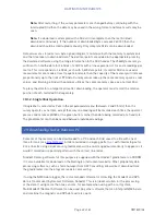
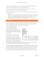
When using the Grad601-2 dual sensor gradiometer for collecting data at 2 or 4 lines/m, the
situation is more complex due to the overlap of the data from the two gradient sensors. The
operator must follow the traverse pattern described below so that the downloading software can
re-arrange the data into the correct positions in the Grid.
Note:
As the surveys can be made in parallel or zigzag, the following description uses the
centre of the beam, or the position of the operator relative to the edge of the Grid, as the
reference point for measurements regardless of direction.
Note:
Surveying a Grid at 2 or 4 lines/m requires proportionally more memory than a
Grid surveyed at 1 line/m, and the number of Grids which can be saved will be reduced
accordingly.


