4. Input & Communication
•
Data and HD sources RGB and YUV [HS/VS, CS or SOG(Y)]:
-
Pixel clock maximum 210 MHz
-
8 bit digital output
•
Video sources CVBS, S-VIDEO, RGB and YUV [CS, CV or SOG(Y)]:
-
PAL B/D/I/G/H, PAL60, PAL M, PAL N, PAL Nc
-
NTSC M/J, NTSC 4.43
-
SECAM B/D/G/K/L
-
525i, 625i, 525p, 625p
-
Macrovision copy protection robust
-
Standard images “video525” and “video625”
•
Automatic detection of sync inputs but with manual override:
-
automatic modes : RGB, YUV, VIDEO
-
manual modes : RGB HS/VS - CS, RGB CV, RGB SOG, YUV HS/VS - CS, YUV CV, YUV SOY, CVBS, S-VIDEO
•
Possible to disconnect 75 Ohm terminations on HS and VS (TTL sync level selection)
•
Signal requirements:
-
Component Video (BNC)
o
R-Y : 0,7Vpp ±3dB 75 Ohm termination.
o
Ys : 1Vpp ±3dB (0,7V Luma +0,3V Sync) 75 Ohm termination.
o
B-Y : 0,7Vpp ±3dB 75 Ohm termination.
-
RG(s)B
o
R : 0,7Vpp ±3dB 75 Ohm termination.
o
G(s) : 1Vpp ±3dB (0,7Vpp G + 0,3Vpp Sync) 75 Ohm termination.
o
B : 0,7Vpp ±3dB 75 Ohm termination.
•
Diagnostic LED’s on front panel:
-
Green LED: Lights up in case input module is selected
-
Yellow LED: Lights up in case sync detected
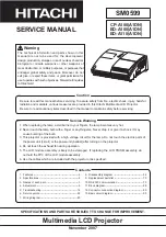
3D Input Module (optional)
Optional 3D input which can be inserted in the free slots.
3D INPUT
R9864140
3D SYNC IN DISPLAYPORT
HDMI
3D SYNC OUT
SYNC
SEL
SYNC
SEL
BARCO
Image 4-4
Signal connectivity
•
3D SYNC IN
BNC socket to apply an external 3D synchronization signal. Used for sequential modes. If signal is not present an internal 3D
sync is generated.
•
DISPLAYPORT
DisplayPort connector to connect a video source.
•
DisplayPort selection LED + sync LED
SEL: lights up if the DisplayPort is selected.
SYNC: lights up if the applied source has a valid DisplayPort sync.
•
HDMI
Connector for HDMI cable (with optional locking mechanism).
•
HDMI selection LED + sync LED
SEL: lights up if the HDMI input port is selected.
SYNC: lights up if the applied source has a valid HDMI sync.
•
3D SYNC OUT
BNC socket. Generates 3D synchronization signal to drive an infra red transmitter for active 3D glasses. In case an 3D syn-
chronization signal is applied on the “3D SYNC IN” for a single channel 3D stream then the generated 3D output sync is derived
from this applied sync.
Input speci
fi
cations
R5905158 HDF SERIES 16/06/2015
43
Summary of Contents for HDF W series
Page 4: ......
Page 10: ...Table of contents 6 R5905158 HDF SERIES 16 06 2015...
Page 44: ...3 Physical installation 40 R5905158 HDF SERIES 16 06 2015...
Page 52: ...4 Input Communication 48 R5905158 HDF SERIES 16 06 2015...
Page 64: ...5 Getting started 60 R5905158 HDF SERIES 16 06 2015...
Page 70: ...6 Quick set up adjustment 66 R5905158 HDF SERIES 16 06 2015...
Page 131: ...9 Image Image 9 103 Time out input R5905158 HDF SERIES 16 06 2015 127...
Page 132: ...9 Image 128 R5905158 HDF SERIES 16 06 2015...
Page 156: ...11 Lamp Image 11 30 Current light output 152 R5905158 HDF SERIES 16 06 2015...
Page 278: ...15 Maintenance 274 R5905158 HDF SERIES 16 06 2015...
Page 304: ...C Standard source files 300 R5905158 HDF SERIES 16 06 2015...
Page 308: ...D DMX chart 304 R5905158 HDF SERIES 16 06 2015...
Page 314: ...E Stacking HDF series projectors 310 R5905158 HDF SERIES 16 06 2015...
Page 318: ...F Environmental information 314 R5905158 HDF SERIES 16 06 2015...