10. Optical adjustments
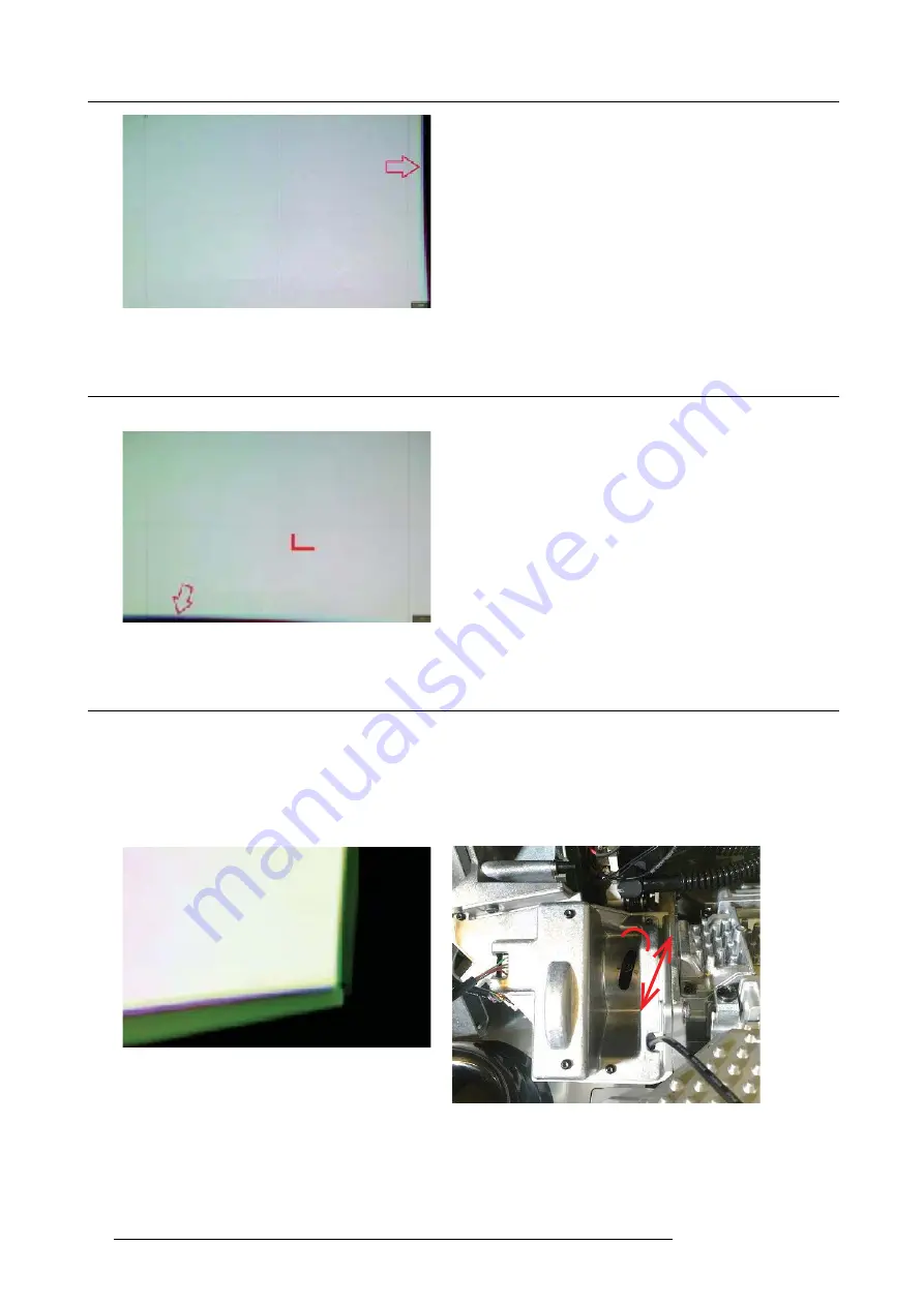
Image 10-2
10.4 Lighting Mirror: Vertical (y) Adjustment
Turn knob (B) with
fi
ngers to adjust mirror vertically until no horizontal band is present in upper or lower edge of image
Image 10-3
10.5 Focus: Relay tube lens focus adjustment
Adjust NUBs (A&B) until the edges of both mirrors are visible in the projected image (See above picture A).
•
- Turn stub screw counter clockwise to loosen (1)
•
- Adjust by pushing stub laterally up/down (2) to
fi
nd the focal point where vertical band
•
- Turn stub screw CW to lock adjustment.
Finalize operation by repeating mirror horizontal adjustment.
Image 10-4
2
1
Image 10-5
44
723–0016 F90 01/12/2017
Summary of Contents for F90 series
Page 1: ...F90 Service Manual 723 0016 02 01 12 2017...
Page 6: ...Table of contents 4 723 0016 F90 01 12 2017...
Page 8: ...1 Introduction 6 723 0016 F90 01 12 2017...
Page 10: ...2 General safety 8 723 0016 F90 01 12 2017...
Page 18: ...4 DLP System General Description 16 723 0016 F90 01 12 2017...
Page 25: ...5 GP6 system functional description Image 5 5 723 0016 F90 01 12 2017 23...
Page 28: ...5 GP6 system functional description 26 723 0016 F90 01 12 2017...
Page 34: ...7 OSD display menu 32 723 0016 F90 01 12 2017...
Page 36: ...8 Thermal management system Image 8 1 34 723 0016 F90 01 12 2017...
Page 42: ...8 Thermal management system 40 723 0016 F90 01 12 2017...
Page 58: ...14 XPS actuator 56 723 0016 F90 01 12 2017...
Page 60: ...15 Light engine 58 723 0016 F90 01 12 2017...
Page 82: ...18 Assembly Hierarchy 80 723 0016 F90 01 12 2017...
Page 103: ...20 Scheduled operations Image 20 42 Image 20 43 723 0016 F90 01 12 2017 101...
Page 104: ...20 Scheduled operations 102 723 0016 F90 01 12 2017...
Page 112: ...21 DMD DMD Board CLGA DMD heatsink elements 110 723 0016 F90 01 12 2017...
Page 132: ...24 Lens shift assembly 130 723 0016 F90 01 12 2017...
Page 134: ...25 Prism Housing Image 25 5 132 723 0016 F90 01 12 2017...


