4. DLP System General Description
4.2
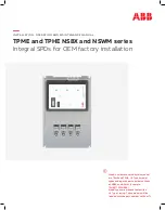
The DMD Device
DMD Device
Image 4-2
At the heart of every DLP™ projection system is an optical semiconductor known as the Digital Micromirror Device, or DMD chip,
which was invented by Dr. Larry Hornbeck of Texas Instruments in 1987.
The DMD chip is probably the world’s most sophisticated light switch. It contains a rectangular array of hinge-mounted microscopic
mirrors, each measuring less than one-
fi
fth the width of a human hair, and corresponding to one pixel in a projected image.
When a DMD chip is coordinated with a digital video or graphic signal, a light source, and a projection lens, its mirrors can re
fl
ect an
all-digital image onto a screen or other surface. The DMD and the sophisticated electronics that surround it are what we call Digital
Light Processing™ technology.
The F90 DMD chip is part of the Texas Instrument DLP9000 family and features over 4 million micromirrors on each chip, offering a
dazzling high resolution 2560 x 1600 (WQXGA) array.
4.3
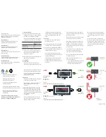
The Grayscale image
Grayscale
Image 4-3
Image 4-4
A DMD panel’s micro-mirrors are mounted on tiny hinges that enable them to tilt either toward the light source in a DLP™ projection
system (ON) or away from it (OFF)-creating a light or dark pixel on the projection surface.
The bit-streamed image code entering the semiconductor directs each mirror to switch on and off up to several thousand times
per second. When a mirror is switched on more frequently than off, it re
fl
ects a light grey pixel; a mirror that’s switched off more
frequently re
fl
ects a darker grey pixel.
In this way, the mirrors in a DLP™ projection system can re
fl
ect pixels in up to 1,024 shades of grey to convert the video or graphic
signal entering the DMD into a highly detailed grayscale image.
4.4
Adding Color
Adding color
Image 4-5
The on and off states of each micro mirror on the DMD chip are coordinated with the three basic building blocks of color – Red,
Green & Blue (RGB). For example, a mirror responsible for projecting a purple pixel will only re
fl
ect red and blue light to the projection
surface. The switching of the mirrors and the proportion of time they are ’on’ or ’off’ is coordinated according to the color shining on
14
723–0016 F90 01/12/2017
Summary of Contents for F90 series
Page 1: ...F90 Service Manual 723 0016 02 01 12 2017...
Page 6: ...Table of contents 4 723 0016 F90 01 12 2017...
Page 8: ...1 Introduction 6 723 0016 F90 01 12 2017...
Page 10: ...2 General safety 8 723 0016 F90 01 12 2017...
Page 18: ...4 DLP System General Description 16 723 0016 F90 01 12 2017...
Page 25: ...5 GP6 system functional description Image 5 5 723 0016 F90 01 12 2017 23...
Page 28: ...5 GP6 system functional description 26 723 0016 F90 01 12 2017...
Page 34: ...7 OSD display menu 32 723 0016 F90 01 12 2017...
Page 36: ...8 Thermal management system Image 8 1 34 723 0016 F90 01 12 2017...
Page 42: ...8 Thermal management system 40 723 0016 F90 01 12 2017...
Page 58: ...14 XPS actuator 56 723 0016 F90 01 12 2017...
Page 60: ...15 Light engine 58 723 0016 F90 01 12 2017...
Page 82: ...18 Assembly Hierarchy 80 723 0016 F90 01 12 2017...
Page 103: ...20 Scheduled operations Image 20 42 Image 20 43 723 0016 F90 01 12 2017 101...
Page 104: ...20 Scheduled operations 102 723 0016 F90 01 12 2017...
Page 112: ...21 DMD DMD Board CLGA DMD heatsink elements 110 723 0016 F90 01 12 2017...
Page 132: ...24 Lens shift assembly 130 723 0016 F90 01 12 2017...
Page 134: ...25 Prism Housing Image 25 5 132 723 0016 F90 01 12 2017...