24. Lens shift assembly
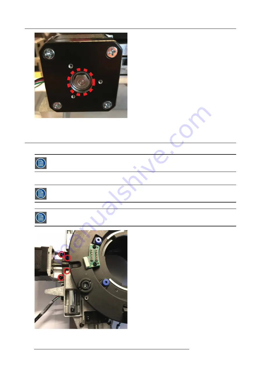
Image 24-2
24.1 Lens shift assembly motors
1. Remove 4 screws (M3x8 TX10 W/Lockw.) to remove lens shift motors with lead screw from lens shft assy.
Dependent on the position of the lens shift mechanism, it may be necessary to manually turn leadscrew to
expose the screws (8mm hex). Accessing these, removal of complete assembly is necessary.
2. Remove 4 screws (M3x8 Tx10) to release lens shift motor from holder.
- Motor for horizontal shift (left) connects to PCB lens hub connector J1
- Motor for vertical shift (lower) connects to PCB lens hub connector J2
Image 24-3
124
723–0016 F90 01/12/2017
Summary of Contents for F90 series
Page 1: ...F90 Service Manual 723 0016 02 01 12 2017...
Page 6: ...Table of contents 4 723 0016 F90 01 12 2017...
Page 8: ...1 Introduction 6 723 0016 F90 01 12 2017...
Page 10: ...2 General safety 8 723 0016 F90 01 12 2017...
Page 18: ...4 DLP System General Description 16 723 0016 F90 01 12 2017...
Page 25: ...5 GP6 system functional description Image 5 5 723 0016 F90 01 12 2017 23...
Page 28: ...5 GP6 system functional description 26 723 0016 F90 01 12 2017...
Page 34: ...7 OSD display menu 32 723 0016 F90 01 12 2017...
Page 36: ...8 Thermal management system Image 8 1 34 723 0016 F90 01 12 2017...
Page 42: ...8 Thermal management system 40 723 0016 F90 01 12 2017...
Page 58: ...14 XPS actuator 56 723 0016 F90 01 12 2017...
Page 60: ...15 Light engine 58 723 0016 F90 01 12 2017...
Page 82: ...18 Assembly Hierarchy 80 723 0016 F90 01 12 2017...
Page 103: ...20 Scheduled operations Image 20 42 Image 20 43 723 0016 F90 01 12 2017 101...
Page 104: ...20 Scheduled operations 102 723 0016 F90 01 12 2017...
Page 112: ...21 DMD DMD Board CLGA DMD heatsink elements 110 723 0016 F90 01 12 2017...
Page 132: ...24 Lens shift assembly 130 723 0016 F90 01 12 2017...
Page 134: ...25 Prism Housing Image 25 5 132 723 0016 F90 01 12 2017...


