When using either the
Points
view or the
Surface
view, left-click, hold, and drag inside the image pane to rotate the image
three-dimensionally. Right-click, hold, and drag to move the image horizontally and vertically.
The histogram graph in the center of the Image Pane Parameters graphically displays the distribution of pixels in the current
image on a scale of amplitude or Z distance, depending on the current view. The white bars can be adjusted left or right to
adjust the shading of the pixels. The histogram is available in all views. The specified operating distance of the sensor is
colored green. A portion of the green bar is a lighter shade of green. The sensor may still return data from this region, but it
may not adhere to the stated accuracy specifications of the device. The green bar is available in
Z(mm)
,
Points
, and
Surface
views.
Use the
Auto
checkbox to automatically scale the pixels to view the entire field of view. When checked, the white shading
control bars are adjusted for each image to start the shading range just before the left-most pixels, and end the shading
range after the right-most pixels in the histogram.
Use the
Clip
checkbox to change what is outside of the histogram graph markers to purple (
Amplitude
and
Z(mm)
views) or
to disappear (
Points
and
Surface
views) to indicate that these areas are not of interest.
The two numbers between the
Auto
and
Clip
checkboxes show the locations of the two white markers in the histogram
graph. These markers can be dragged to the desired location.
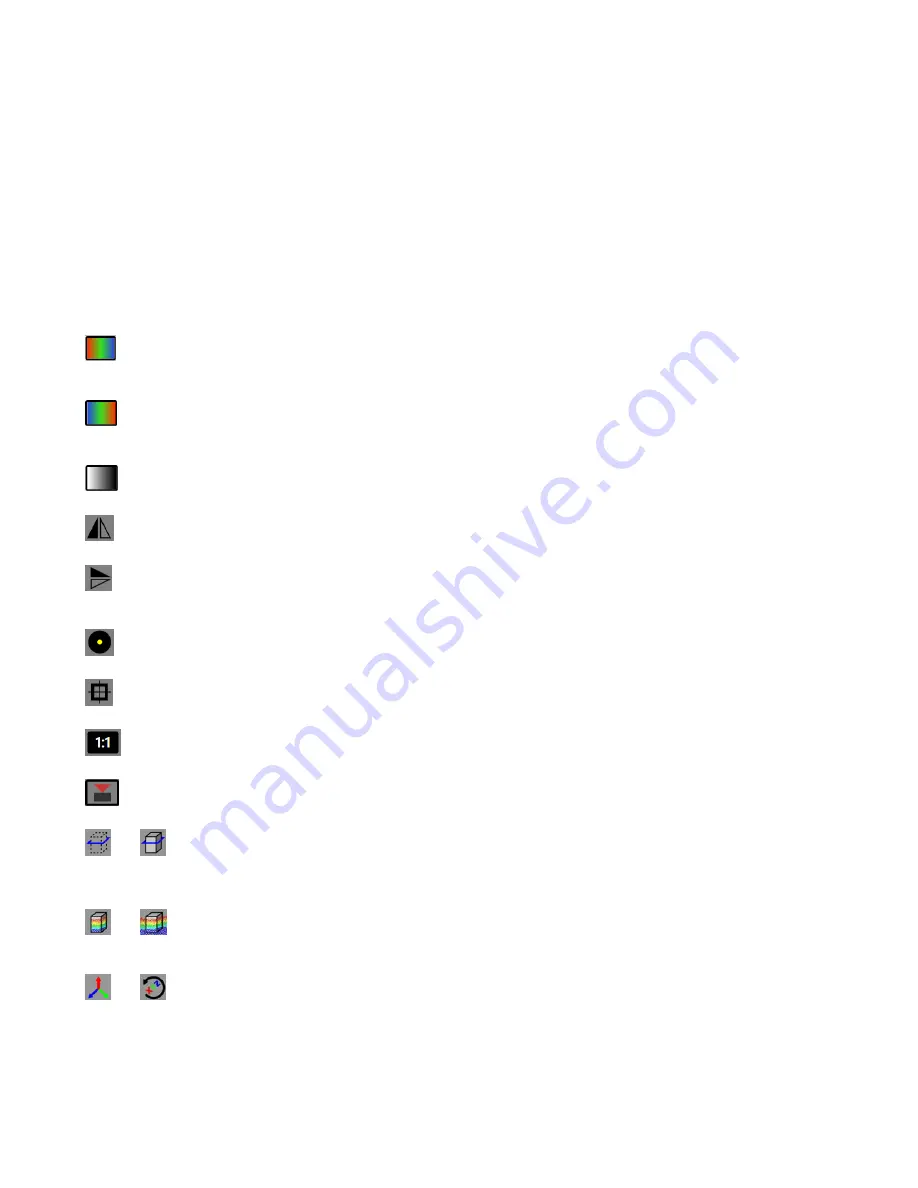
- Red is Near, Blue is Far—Displays objects closest to the sensor as red, while objects further from the sensor display
as blue. Objects between these points display in various colors, depending on their distance from the sensor. Available in
Z(mm)
,
Points
, and
Surface
views.
Blue is Near, Red is Far—Displays objects closest to the sensor as blue, while objects further from the sensor display
as red. Objects between these points display in various colors, depending on their distance from the sensor. Available in
Z(mm)
,
Points
, and
Surface
views.
Grayscale Overlays Distance—Changes the image color scheme to grayscale. Available in
Z(mm)
,
Points
, and
Surface
views.
Horizontal Flip Mode—Changes the view to a horizontal mirror image of the true view—the objects that were on one
side of the view are now shown on the other side. Available in all views.
Vertical Flip Mode—Changes the view to a horizontal mirror image of the true view - the objects that were on one side of
the view are now shown on the other side—what was showing on the top of the screen is now showing on the bottom of the
screen. Available in all views.
Bubble Level On/Off—Shows or hides a level on screen at the cursor location that updates as the sensor is tilted.
Available in
Amplitude
and
Z(mm)
views. Default is off.
Image Center Crosshairs On/Off—Shows or hides crosshairs that indicate the center of the field of view of the sensor.
Available in
Amplitude
and
Z(mm)
views. Default is off.
Toggle 3D point cloud display decimation levels—Changes the size of the points shown. Available in
Points
and
Surface
views. Does not change image acquisition parameters. Default is 2:1.
Show or hide the 3D camera—Shows or hides the position of the sensor over the container as well as the field of view.
Available in
Points
and
Surface
views. Default is hidden.
and
Hide or show the application working volume sidewalls—Shows or hides the user-defined boundaries of the
container. This view also shows two colored boxes. The first is the Z-height setting shown as a green box. This box turns to
red when the peak height is reached. The second is the fill level shown as a blue box that moves as the container is filled or
emptied. Available in
Points
and
Surface
views. Default is show.
and
Hide or show all points outside of the application 3D Space—Show or hide objects that are within the field of
view of the sensor but are located outside of the defined boundaries of the container. Available in
Points
and
Surface
views.
Default is show.
and
Reset 3D camera view—Resets the 3D view to the default X, Y, and Z positions.
Coordinates in the Amplitude and Z(mm) Views
—The following display in the lower right in the Amplitude view.
Amp
Brightness level of the selected pixel. The Amplitude range is 10 to 3000.
ZMX Series 3D Time of Flight Sensor
12
www.bannerengineering.com - Tel: + 1 888 373 6767


