


LED indications 18
LED indications
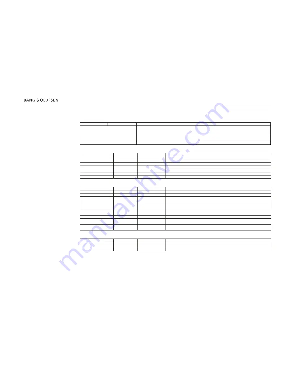
Power Link LED indications
White ~ left speaker
Red ~ right speaker
Comment
Off
Sound channel is inactive after power up
Not configured yet i.e. during manual configuration
Normal operation
On
Solid light after scanning and storing; turns Off after 10 s time-out
Also shown when checking for connected speakers: long press on
STORE
Flashing
During manual configuration or if a speaker is not configured
WIRELESS LED indications
State
Signal
Time
Comment
Configured wirelessly
-
-
Product is configured wirelessly
Standby
Off
-
Product is in standby mode
Normal operation
White (solid)
Off after 10 s time-out
After pressing
STORE
: Speaker connections behave normally
Normal operation
White (slow flashing)
200 ms/200 ms
No speakers are connected
Connecting
Green
(fast flashing)
100 ms/100 ms
In setup (scanning) mode and open for connecting speakers
Network strength is low
Orange
(solid)
-
Connection quality in network is low
Network failure
Orange
(fast flashing)
100 ms/100 ms
Network error or some malfunctioning e.g. subwoofer not found in a SUB 2.1 setup
Product Status LED indications
State
Signal
Time
Comment
Power Link Transmitter 1 is Off
-
-
Product is switched Off
Standby
Off
-
Product is in standby mode
Normal operation
Off
-
Product behaves normally
Mains On and
Restart after Reset
Red
(solid)
Off after 10 s time-out *
Lit when power is applied to the BeoLab Transmitter 1, to indicate that it is switched On and becomes
ready for operation
Also lit when reset either by the user (external) or by the BeoLab Transmitter 1 (internal)
Turning Off (go to Standby)
Red
(solid)
Off after 10 s time-out *
Lit when switching Off either via Power Link from the source product or when the signal is no longer
present (i.e. silence in 15 minutes)
Turning On
Green
(solid)
Off after 10 s time-out *
The BeoLab Transmitter 1 is switched On and has sensed an input
Software Update
Green
(slow flashing)
200 ms/100 ms
Off when done
Indicate that the power must not be disconnected during the update process
Product failure
Orange
(fast flashing)
100 ms/100 ms
Hardware error - product will not revert to normal operation or if revert automatically to normal
operation : see ERROR LOG in ServiceTool
Product Status LED and WIRELESS LED indications simultaneously
State
Signal
Time
Comment
Network strength low /
poor wireless range
Orange
(solid)
-
System connection quality is low. Distance to speaker(s) too long
Network failure
Orange
(fast flashing)
100 ms/100 ms
Network error or other malfunctioning
* The WIRELESS LED indicator will not go Off within time out or automatic standby mode, during the setup process.
(See
page 4
and
page 16
)
(See
page 4
)
(See
page 4
)