background image

Setting up and connecting BeoLab Transmitter 1     14

Setting up and connecting BeoLab Transmitter 1

An interactive video on setting up connections to BeoLab Transmitter 
1 is found on 

www.bang-olufsen.com/interactive-guide/


Setting up the BeoLab Transmitter 1

TV product as the source

-  Ensure the speakers are set to WIRELESS.
-  Ensure all speakers and the BeoLab Transmitter 1 are disconnected 

from mains.

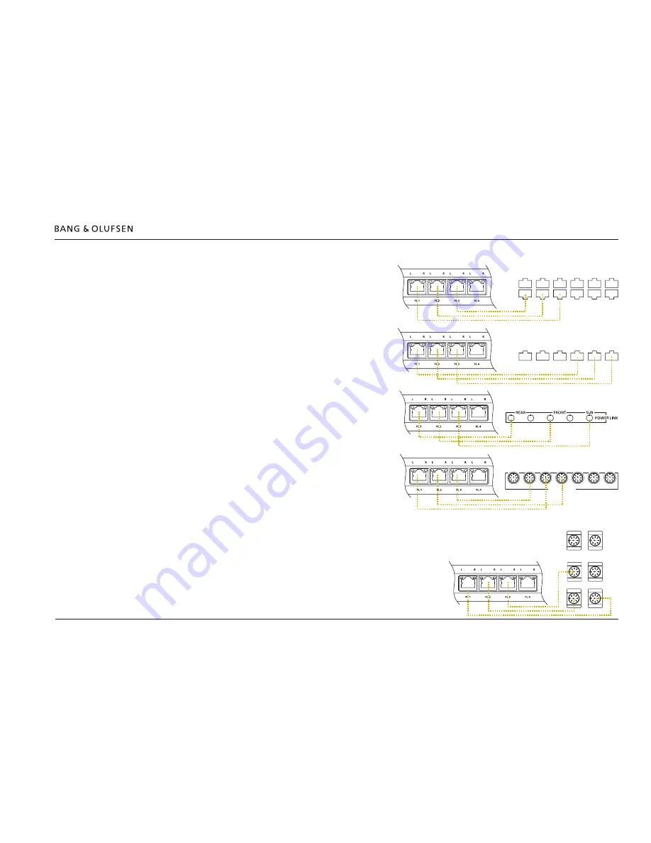
-  Connect the BeoLab Transmitter 1 to the source product (TV or audio 

master) using appropriate Power Link cables

, TOSLINK or RCA cables.

-  Cables in both BeoLab Transmitter 1 and Bang & Olufsen source 

product must be in numerically increasing order; i.e. PL 1 to PL 1, Start 

with the PL 1 socket and fill in the PL sockets from left to right. 
Predefined Power Link sockets are likewise connected to the PL 1, PL 2 

sockets etc. It is recommended to place cable with the subwoofer 
source signal in the rightmost Power Link socket of the sockets used.  

TOSLINK or RCA cables are connected to their matching connectors.


Advice: Keep a record of cables and Power Link sockets.

- Set 

B&O INPUT

 switch to 

YES. 

When the source is not a Bang & 

Olufsen product the 

B&O INPUT

 switch must be set to 

NO. 

When set to 

YES

 the BeoLab Transmitter 1 reacts to the PL signal 

Speaker On/Off. When set to 

NO

 the BeoLab Transmitter 1 reacts to 

the signal level in the speaker channels (sound/noise).

-  When source input comes to more Power Link sockets, the 

SUB 2.1


switch is set to 

OFF

.

Audio product as the source (see next page)

-  Set the 

SUB 2.1

 switch to 

ON

 when the input is a stereo signal and the bass 

management function of the BeoLab Transmitter 1 is providing the signal to a wireless 
subwoofer in the third sound channel PL2 L.

-  Connect mains to all speakers and the BeoLab Transmitter 1. The WIRELESS LED will 

start flashing white during the configuration process. 

PL 5

PL 4

MONITOR

CONTROL

PUC 2

A+B

PUC 1

A+B

EXT. IR

PL 3

PL 2

PL1

PUC 3 A+B

CTRL 3

CTRL 2

CTRL 1

BeoLab Transmitter 1

BeoVision 11 

CTRL 1

PUC2 A+B

CTRL 3

PUC1 A+B

CTRL 2

PL1 

PL2 

PL3

BeoLab Transmitter 1

BeoPlay V1 

BeoLab Transmitter 1

BeoVision 10 

POWER LINK

CENTRE 1

1(SUB)

2

3

4

5

6

BeoLab Transmitter 1

BeoVision 7-40 MKIII to MKIV and TV 

REAR

FRONT

SUBWOOFER

REAR

SURROUND SOUND SPEAKERS

FRONT

CINEMA

CENTRE

BeoLab Transmitter 1

BeoVision 7-40 to MKII 

Summary of Contents for Beolab transmitter 1

Page 1: ...BeoLab Transmitter 1 Type 1505 1513 Installation Guide English version 1 1 31 0 3 4 16 7...

Page 2: ...ossible to configure up to 11 wireless speakers to the sound channels as desired One scenario may be a 7 4 setup One switch is used to shift between a Bang Olufsen Power Link signal in and a line in s...

Page 3: ...her feature to optimise the navigation is the navigation icons at the bottom of the screen see below for explanation Navigates you to the previous view Navigates you directly to the start page Navigat...

Page 4: ...gives indications regarding the left L channel and the red LED gives indications regarding the right R channel see LED indications page 18 The Wireless Power Link antennas are placed in the lid top o...

Page 5: ...d with a distance of 260 mm 10 6 See also the setting up guide enclosed in the packaging for the BeoLab Transmitter 1 The BeoLab Transmitter 1 can be placed vertically or horizontally The cable cover...

Page 6: ...between the BeoLab Transmitter 1 and the speakers especially not objects consisting of material that will block or totally reflect the wireless signals Setting listening distance to speakers In most T...

Page 7: ...itch to OFF With a stereo only signal as input and a wireless subwoofer available set the SUB 2 1 switch to ON The bass management function of the BeoLab Transmitter 1 provides the subwoofer signal to...

Page 8: ...NPUT switch to NO SUB 2 1 With a multiple sounc channel as input set the SUB 2 1 switch to OFF With a stereo only signal as input and a wireless subwoofer available set the SUB 2 1 switch to ON The ba...

Page 9: ...uct is connected additional to the 3rd party product the switch is set to YES SUB 2 1 With a stereo only signal as input and a wireless subwoofer available set the SUB 2 1 switch to ON The bass manage...

Page 10: ...oduct is connected additional to the 3rd party product the switch is set to YES SUB 2 1 With a stereo only signal as input and a wireless subwoofer available set the SUB 2 1 switch to ON The bass mana...

Page 11: ...o 11 speakers may be arbitrarily configured to be connected to the available source channels Examples of source input are Stereo input no bass management SUB 2 1 set to OFF This provides a left and a...

Page 12: ...d for configuration of the left and right sound channel for each of the PL socket in a multi channel setup Manual configuration Long press SELECT to start manual configuration The WIRELESS LED turns s...

Page 13: ...el and the red LED for the right sound channel switches Off after approx 10 s Subwoofer sound channel The white LED L above the PL2 socket is indicating the subwoofer sound channel Short press once or...

Page 14: ...er Link sockets Set B O INPUT switch to YES When the source is not a Bang Olufsen product the B O INPUT switch must be set to NO When set to YES the BeoLab Transmitter 1 reacts to the PL signal Speake...

Page 15: ...icator on the speakers will turn into solid green and then be turned Off after 10 s time out The speakers are now connected to the BeoLab Transmitter 1 although the speaker role is not matched with th...

Page 16: ...e to be configured The below example illustrates the Power Link LED indications when speaker for the 3rd sound channel is being configured Speaker setup in TV menu BeoVision 7 40 Press Menu OPTIONS SO...

Page 17: ...e with next channel Store X long 1 5 s and 10 s Configuration mode Stores the configuration of the match between the sound channel and a speaker and remain on same channel to be matched with another s...

Page 18: ...dby mode Normal operation Off Product behaves normally Mains On and Restart after Reset Red solid Off after 10 s time out Lit when power is applied to the BeoLab Transmitter 1 to indicate that it is s...

Page 19: ...eoLab Transmitter 1 to the mains Connect the USB Mini B connector Service of the BeoLab Transmitter 1 to a USB A connector of the PC hosting the ServiceTool Identify the Com port used on the PC by ent...

Page 20: ...Status LED will be slowly flashing green during the update process Sometimes two updates are initiated and the LED will be slowly flashing green during the second update process LEDs over the Power L...

Page 21: ...b Transmitter 1 and disconnect all wireless speakers where the LED is quickly flashing green from the mains for at least 60 s Reconnect all wireless speakers to the mains Reconnect the BeoLab Transmit...

Page 22: ...level A list of compatible TVs can be seen on BeoWise By the IR eye it becomes possible to control volume up and down and also to mute and un mute the setup When returning from muted state the volume...

Page 23: ...tting and log files see page 24 A USB memory stick is needed having a file in the root with the name WPLSETUP TXT and this file shall contain the command line text ALWAYS ON TRUE Disconnect the BeoLab...

Page 24: ...s the WPLSETUP TXT file and the settings for line in are set in the BeoLab Transmitter 1 A file named WPL_DUMP TXT will be created on the USB memory stick or alternatively overwrite the existing file...

Page 25: ...Lithuania Luxembourg Monaco Norway Oman Poland Portugal Romania Saudi Arabia Serbia Slovak Republic Slovenia Spain Sweden Switzerland Turkey 1507 Botswana Ghana Ireland UK HF3 1505 Bahrain Chile Egyp...

Page 26: ...computers is regarded a transmission system The distance between a 5 GHz transmitter and a speaker must be no more than 12 metres 40 ft see page 6 The stereo surround sound setup must be within an are...

Page 27: ...Band to scan in the 5 GHz band Press Wi Fi and select the net board of your computer in this example Intel R Centrino R Advanced N 6205 to enable the on board WLAN Click on the tool to have the Displ...

Page 28: ...Site survey Wi Spy 28 Channel No s Display selected networks Colouring by Density Wi Fi Channels Full 5GHz band set check mark...

Page 29: ...500 mA used for SW update Pin 1 5 V V Bus Pin 2 Data Pin 3 Data Pin 4 GND Shield GND PL 1 4 RJ45 used for Power Link Pin 1 Overload Pin 2 Data High 3 5V Low 0 8V Pin 3 Signal GND Pin 4 Speaker On Off...

Page 30: ...rear side Demount from wall mounting Mounting Table of Contents Version 1 1 2014 06 Table of Contents Introduction 2 How to use this installation guide 3 BeoLab Transmitter 1 front 4 BeoLab Transmitt...

Reviews: