Technical staff manual
28
13.2
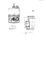
Main components
13.2.1. Control system
Device
Purpose
Electronic board 11 (see p. 13.1, page 27)
Boiler operation control and providing safety in case of emergency
situations appearance
Electric wiring
A set of wires for connecting the electronic board to the sensors,
devices and mechanisms
13.2.2. Hydraulic system
Device
Purpose
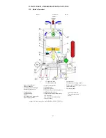
Heat exchanger 2
Heat transmission, appearing at gas combustion, to the heat carrier
Secondary heat exchanger 3
Heat transmission from the heat carrier of the heating system to the
water of DHW system
Pump 7
Device for creating forced heat carrier circulation
Air outlet valve 8
Automatic air removal from the heating system
3 way valve 18 with an electrical motor
19
Switching over the heat carrier flow from the primary heat exchanger
between the heating and DHW systems
Expansion tank 10
Compensation of the heat carriers expansion due to heating
13.2.3. Gas system
Device
Purpose
Burner block (burner) 4
Mixing air with gas and providing equable combustion of the gas and
air mixture in the combustion chamber
камере сгорания
Ignition transformer 12
Forming the electric spark on the ignition plug
Ignition plug 5
Forming the electric spark for igniting gas and air mixture on the
burner
13.2.4. Smoke exhausting system
Device
Purpose
Fan 28
Forced combustion products exhaustion
Gas removal device 1
Atmospheric combustion products exhaustion
13.2.5. Regulation devices
Device
Purpose
On gas
Gas supply regulator 9 (see p. 13.1, page
27)
Regulating gas supply to the burner block
On the heat carrier
CH temperature sensor 16
Changing the heat carrier temperature.
The signal from the sensor is used for maintaining the set heat carrier
temperature in the CH
On water
Temperature sensor of DHW supply
circuit 17
Measuring water temperature in the DHW supply circuit.
The signal from the sensor is used for maintaining the set temperature
in the DHW supply circuit
Flow sensor of DHW supply 23
Defining water flow in the DHW supply circuit.
The signal from the sensor is used for rendering the boiler to the DHW
supply mode at hot water tap opening
Summary of Contents for NEVALUX-8230
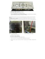
Page 35: ...Assembly is performed in reverse order Scheme 23 Heat exchanger dismantling...
Page 41: ...48...
Page 47: ...Ignition and ionization plugs in the assembly pos 67...
Page 54: ......
Page 55: ......

