Technical staff manual
29
13.3.Service functions
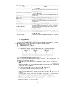
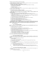
13.3.1.Parameters programming function
The parameters programming function permits to change the main launch and operation parameters of the boiler.
This function works only in the standby mode and permits to change the following parameters:
“P0” – ignition power 0 - 99 (100 steps);
“P1” – minimal heating power 0 - 39 (40 steps);
“P2” – maximum heating power 40 - 99 (60 steps);
“P3” – minimal time from switching off to the next putting into operation 0 - 14 (min). Factory settings:
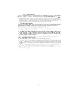
For using the parameters programming function it is necessary to:
1)
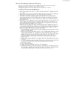
Switch the boiler off, consequently pressing the button К5 (see Scheme 3, page 8) until the symbol
appears on the boiler’s display.
2)
Disconnect the boiler from the power line;
3)
Connect the boiler to the power line again. For 5 seconds there is a possibility to activate the programming
function;
Technical staff manual
4)
Press and simultaneously hold the DHW and heating temperature reduction buttons (К2 and К4) for activating
the parameters programming function;
5)
Quit hold of the buttons, when the code “P0” and the symbol
appear on display;
6)
Choose the parameter that must be changed, pressing the buttons КЗ or К4;
7)
Press the button К5, in order to see the parameter value on display. The symbol
on display will start
flickering;
8)
Change the chosen parameter’s value, pressing the buttons К1 (value increase) or К2 (value reduction). In
order to increase speed of parameter changing you may press and hold the buttons К1 or К2;
9)
Press the button К5, in order to keep the set parameter value and return to choosing parameters;
10)
Repeat the cycle, beginning from point 6, in order to modify all parameters that you want to change;
11)
Press the button К6 (RESET) in order to exit the programming mode.
Do not change the parameter Р3 with no extreme need.
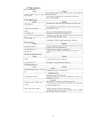
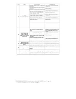
13.2.6. Safety devices
Device
Purpose
For control
Safety catch 21 ( see Annex III, page 66)
Protecting the electronic board and electric circuits from the power line
surcharge and short circuit
For the heat carrier
Pressure sensor 14
Minimal heat carrier pressure control and control of absence of air in the
heating system
Thermorelay 15
Protecting primary heat exchanger from overheating
Bypass valve 20
Protecting primary heat exchanger from overheating at increased
resistance in the heating system
Safety valve 22
Spilling the heat carrier from the heating system when the pressure is
higher than 3 bar
Air outlet valve 8
Automatic air removal from the heating system
For gas
Gas supply regulator 9
Ignition at reduced pressure in order to avoid the “clap”. Blocking gas
supply when a dangerous situation appears (heat carrier overheating,
absence of draught etc.)
Ionization plug 6
Burner flame control.
Cease of gas supply to the burner when there is no flame
For combustion products
Air pressure switch 27
Fan operation control.
Cease of boiler operation in case of no draught or the fan’s breakdown
Parameter
Natural gas
Liquefied gas
P0
40
60
P1
0
0
P2
99
99
P3
3
3
Summary of Contents for NEVALUX-8230
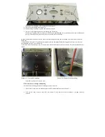
Page 35: ...Assembly is performed in reverse order Scheme 23 Heat exchanger dismantling...
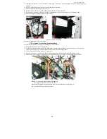
Page 41: ...48...
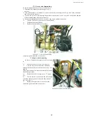
Page 47: ...Ignition and ionization plugs in the assembly pos 67...
Page 54: ......
Page 55: ......

